Determining the utility of an equivalent-circuit model versus construction reality is often a difficult challenge.
Using simplified, first-order approximations in models and equivalent circuits is a normal part of engineering life. Without them, we would get mired in the details and harsh reality of the components and their characteristics. We would never be able to take those critical, rough-estimate first steps; instead, the well-known “paralysis by analysis” syndrome would take over.
This is especially the case for the complex equivalent circuits and their subtleties of RF designs — where the parasitics of just a few picofarads or nanohenries are critical — and in solid-state device physics, to cite two areas. But such fidelity concerns are for other disciplines as well, and it’s easy to get comfortable when looking at equations associated with these simplifications very easily.
Consider a simple wire loop: after all, there’s not much which is simpler than that. Its attributes adhere to Maxwell’s equations (perhaps better described as Oliver Heaviside’s reduction of Maxwell’s twenty-plus extremely complex equations to the four classic ones we know, but that’s another story; see “Twenty Three Years: The Acceptance of Maxwell’s Theory” and “Oliver Heaviside: A first-rate oddity“).
Nonetheless, even that simple wire loop — whether implemented in a basic paired-coil transformer, an RF inductor, or a toroidal transformer — has a reality that goes far beyond the first-order model commonly used to describe it. Thus, deciding when the model is “good enough” for the application is often a difficult engineering decision.
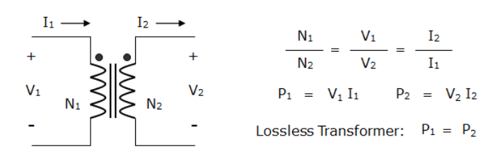
One of the first things taught in basic EE class is the basic transformer-turns equations where the ratio of the number of primary turns N1 to the number of secondary turns N2 defines the step-up/step-down voltage and impedance ratio, (Figure 1). That simple equation makes for a good start at characterizing the transformer’s behavior and what it does for a circuit or power subsystem.
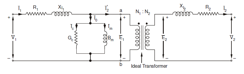
Nonetheless, it’s naive to assume that all you need is N1/N2 for transformer design. This ratio serves as a vivid reminder that simplifications are good and necessary, but they are only starting-point approximations to a somewhat more-complete equivalent circuit (Figure 2).
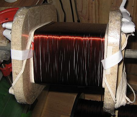
It would be great news if an equivalent-circuit model, even a complicated one, could fully capture the transformer’s reality with near-perfection. However, transformers also have challenging mechanical and insulation requirements to meet plus the vagaries of construction, which complicates their design idea versus as-built performance (Figure 3). These include winding issues due to wire gauge, insulation type and thickness, evenness and symmetry, thermal-induced changes, and more (see References 5 and 6).
Achieving the high levels of performance often needed requires both a deep dive into the underlying equivalent-circuit model as well as the hands-on approach of build-evaluate-redo (and then repeat until satisfied). That’s where models fall short and designers must also rely on experience, rules of thumb, approximations, and estimates.
Equivalent-circuit models and hard-learned reality complement the other’s strengths and weaknesses. Of course, with the quality of many of today’s modeling tools and the powerful processors that execute them, the former approach is gaining more adherents: it can save time and money, reduce frustration, and allow more “what-if” analysis of changes in parameters and their associated tradeoffs.
Calculating the specifics for a custom transformer, and then winding it yourself is an educational, satisfying, and frustrating experience, in varying proportions. One thing is sure: you’ll never say “no big deal…it’s ‘just’ a transformer” again.
External References
- “Build Your Own Transformer” – not sure why you would ever want to after reading this but you might have to, for a special application.
- “Analysis and Loss Mechanism of a Spiral Inductor Via the Green’s Function Model” – some truly serious math here.
- “Calculating the High-Frequency Resistance of Single and Double Layer Toroidal Windings” – also pretty deep stuff.
- “Designing a Discontinuous-Conduction-Mode Flyback Transformer” – in this power-supply topology, the transformer is the basic two-winding voltage transformer, and also an energy-storage inductor, with a more advanced model.
- “Transformers and coils” is an excellent introduction to the technology, art, and craft of DIY transformer winding and is a pre-cursor to the next item on this list.
- “Practical transformer winding” – a very serious and skilled amateur shows how he winds his own transformers; gives you a real sense and appreciation for what’s involved if you do it manually with various jigs and fixtures.
Related EE World Content
Transformers for ultrasonic sensing applications
Gate drive transformer specifications and applications
RF transformer specifications – Making the best of a non-ideal situation (Part 3)
Dealing with non-ideal transformers – Basic RF transformer theory of operation
What are the telegrapher’s equations?


Leave a Reply
You must be logged in to post a comment.