• Skip to primary navigation
  • Skip to main content
  • Skip to primary sidebar
  • Skip to footer

Electrical Engineering News and Products

Electronics Engineering Resources, Articles, Forums, Tear Down Videos and Technical Electronics How-To's

  • Products / Components
    • Analog ICs
    • Connectors
    • Microcontrollers
    • Power Electronics
    • Sensors
    • Test and Measurement
    • Wire / Cable
  • Applications
    • Automotive/Transportation
    • Industrial
    • IoT
    • Medical
    • Telecommunications
    • Wearables
    • Wireless
  • Resources
    • DesignFast
    • Digital Issues
    • Engineering Week
    • Oscilloscope Product Finder
    • Podcasts
    • Webinars / Digital Events
    • White Papers
    • Women in Engineering
  • Videos
    • Teschler’s Teardown Videos
    • EE Videos and Interviews
  • Learning Center
    • EE Classrooms
    • Design Guides
      • WiFi & the IOT Design Guide
      • Microcontrollers Design Guide
      • State of the Art Inductors Design Guide
    • FAQs
    • Ebooks / Tech Tips
  • EE Forums
    • EDABoard.com
    • Electro-Tech-Online.com
  • 5G

Where are wire-to-board connectors used?

January 27, 2022 By Mary Gannon

Wire-to-board connectors are used to connect a wire or group of discrete wires to a printed circuit board (PCB). These connectors serve as an efficient and cost-effective method for delivering power and signals to PCBs in automotive, industrial, lighting, and communication products. Commercial electronic equipment and household appliances often use wire-to-board connectors as well.

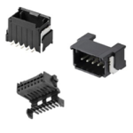
wire-to-board connectors shutterstock_2075457535The needs of the application will dictate the style of connector chosen, as there are no “standard” wire-to-board connector designs. Depending on the manufacturer, some feature low-profile mating for tight spaces and various locking mechanisms such as friction lock, full lock, or quick disconnect. Others feature a locking bar or snap-fit type of connection to ensure the wire remains securely in its socket. While many connectors are surface mounted to the board, others have pins that go through the board and are soldered to the other side.

Wire-to-board connectors are specified by properties such as housing size, materials, number of contacts, stacking height (height of connector measured from the circuit board), length of contacts, and number of contact rows. They are also specified in terms of pin pitch, which is the distance measured between the centers of two conductors. Wire termination also differs based on the wire size and number of contacts. For example, connectors that handle significant power often have crimped-on contacts that are secured with some sort of tool. Other styles, such as mass termination connectors that hold 20 wires or more, can be designed for use in automated soldering systems.

Another recent development is a new generation of ultra-compact connectors with profiles under 1.5 mm that are compatible with automated surface mount assembly in high-volume manufacturing. To ensure reliability, these tiny connectors often feature gold-plated contacts and strain relief capabilities. With so many sizes and styles available among today’s wire-to-board connectors, design engineers have more options than ever to select the right power and signal delivery system for their end products.

You may also like:


  • Heilind Electronics stocking Molex Micro-One wire-to-board connector system
DesignFast Banner version: 03d74fcc

Filed Under: Connector Tips, FAQ, Featured

Primary Sidebar

EE Training Center Classrooms

EE Classrooms

Featured Resources

  • EE World Online Learning Center
  • CUI Devices – CUI Insights Blog
  • EE Classroom: Power Delivery
  • EE Classroom: Building Automation
  • EE Classroom: Aerospace & Defense
  • EE Classroom: Grid Infrastructure
Search Millions of Parts from Thousands of Suppliers.

Search Now!
design fast globle

R&D World Podcasts

R&D 100 Episode 7
See More >

Current Digital Issue

Our second 5G Handbook is now available

Featuring 15 articles, the 2022 5G Handbook looks at private networks, timing, connectivity, latency, mmWaves, test, and other topics.

Digital Edition Back Issues

Sponsored Content

Positioning in 5G NR – A look at the technology and related test aspects

Radar, NFC, UV Sensors, and Weather Kits are Some of the New RAKwireless Products for IoT

5G Connectors: Enabling the global 5G vision

Control EMI with I-PEX ZenShield™ Connectors

Speed-up time-to-tapeout with the Aprisa digital place-and-route system and Solido Characterization Suite

Siemens Analogue IC Design Simulation Flow

More Sponsored Content >>

RSS Current EDABoard.com discussions

  • about ATmega328 ADC pins
  • Tuning the antenna to be conjugately matched to input impedance of the die
  • Netlist physical name update
  • nt1065_USB3 gnss receiver
  • LLC HB with synchronous rectifiers can be very dodgy?

RSS Current Electro-Tech-Online.com Discussions

  • undefined reference header file in proteus
  • Capacitor to eliminate speaker hum
  • Decapped Chip On Board
  • Sony KV-A2913E (chassis AE1C) auto shuts off after one minute
  • CRT TV repair

Oscilloscopes Product Finder

Footer

EE World Online

EE WORLD ONLINE NETWORK

  • 5G Technology World
  • Analog IC Tips
  • Battery Power Tips
  • Connector Tips
  • DesignFast
  • EDABoard Forums
  • Electro-Tech-Online Forums
  • Engineer's Garage
  • Microcontroller Tips
  • Power Electronic Tips
  • Sensor Tips
  • Test and Measurement Tips
  • Wire & Cable Tips

EE WORLD ONLINE

  • Subscribe to our newsletter
  • Lee's teardown videos
  • Advertise with us
  • Contact us
  • About Us
Follow us on TwitterAdd us on FacebookConnect with us on LinkedIn Follow us on YouTube Add us on Instagram

Copyright © 2022 · WTWH Media LLC and its licensors. All rights reserved.
The material on this site may not be reproduced, distributed, transmitted, cached or otherwise used, except with the prior written permission of WTWH Media.

Privacy Policy