The latest high-speed transmission cables are benefitting from the use of optic-fiber and copper wire options, which are offering unique form factors and customizable solutions.
Typically, data-transmission copper wire and optical-fiber conductors are round or cylindrical. The addition of silver plating on the copper conductor facilitates the high-frequency electrical transmission path. Fiber conductors are foundry drawn with gasified rare elements that, along with the outer clad, ensure photons go through the optical fiber in a helical wave.
For the most part, signal integrity engineers advise using the same transmission geometry between the chip, board, bulkhead IO faceplate, and the next box. Minimizing geometry transition zones supports a better overall signaling performance and link reach budget with lower dB loss numbers.
Termination techniques
The copper-conductor termination method selected can offer significant value to process-manufacturing engineering and production capabilities, supporting a healthy return on investment. Of course, the choice will be affected by the application, including dwell times, temperature ranges, tooling sizes, equipment types, and the chemistry options. This is usually covered in the NDAs.
Interestingly, some suppliers figured out how to weld a round-shaped conductor wire to a pluggable connector’s PCB pad instead of soldering. For several years, soldering or welding the round, silver-plated, twin-axial conductor wires to the flat pad meant having a smooth, balanced solder fillet or weld joint. These are still used in some applications.
However, it’s also not uncommon to now “coin” the end of a round-wire conductor to better match the plug connector contact’s stamped geometry design. Sometimes the contacts are coined to closely match the geometry of a round conductor.
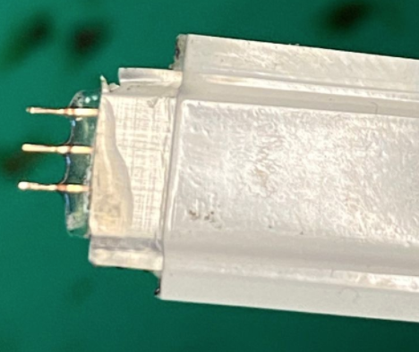
By using the wide, hot-bar solder-reflow method, Meritec’s 50 twin-axial paired a modified MDR connector with a center ground bar, using contacts that were well-matched with the tapered round-wire termination zone. This high-speed cable assembly was selected and used for two-speed rates of the once-popular NumaLink IO interfaces.

To match the developments of higher-generation IO speed rates, there was a critical need for more symmetrical copper-circuit terminations, extremely small termination zones/pads, as well as smaller contacts and connectors. This also drove the need for CX-4 and pluggable IEEE-802.3 Ethernet connectors and cables.
Advanced geometry terminations began including conductor butt to contact butt red YAG welding laser, which had a minor soot issue, but was partially replaced with a cleaner green YAG welding laser and automated equipment. The welded wire and contact relied on intermolecular fusion without soldering. If necessary, a dab of quality silver paint (closely matching the copper core’s silverplate) could be applied to the welded zone for higher-speed signaling performance.
Other termination methods used included electrical-resistance solder reflow, hot air-knife solder reflow, and hydrogen micro-flame torch.
More recent advances in automation have improved precision-laser trimming of the shields, conductors, insulations, machine vision, and inline production testing. Some manufacturers have linked their automated two-connector and cable manufacturing lines into one cable assembly line to support the higher volumes now required, particularly for the data-center industry.
There’s also an increasing demand for flat or rectangular conductors to support the 56 and 112G per-lane copper, differential-paired applications in smaller form-factor equipment.
It’s likely such products will be used for the next generation of internal, video-standard interfaces and applications. Rather than FFC and FPC connectors and cables, they’ll likely require advanced flat and ribboned cables. This is because flat cable conductors usually terminate with greater ease and reliability to flat PCB pads, at least in terms of signal integrity.
In fact, flat RF wire 75 and 50ohm options are already available. A better insertion loss is achievable than with standard round-coax wire at the same thickness. Currently, oval, ovoid, ellipse, knurl, and other conductor geometry designs are also being evaluated for specific applications.
New developments
The use of round, hollow-core fiber has increased dramatically as it’s proven about 50% faster, optically, than standard solid-glass fiber. This is particularly significant for FinTech (financial technology) cable network systems, commonly used by investors, financiers, banking institutions, and betting applications.
A meticulous hollow-fiber termination process is necessary for alignment in laser devices. Precision fiber-to-fiber alignment is critical to meet the dimensional uniformity requirements with 8, 16, and 32+ optical hollow-core fiber connector and cable assemblies.
The growth in advanced data centers has led to greater use of fibers for different topologies and accelerator interfaces. For example, the newer high-radix switch topologies require more optical modules and cables. This has resulted in complexity and higher cost factors, which is leading some in the market to consider other options, such as multi-core round cables (8, 16, 32+ cores).
Miniaturization and meshing have given rise to the 106G per-lane IEEE-802.3cu specification. The developing IEEE-802.3df 212G per-lane spec will work to support single and multi-lambda lambda single-fiber applications. So, there’s an optical link design that now uses several fibers per cable and silica cores per fiber, along with 1, 4, 8, 16+ lambda single-fiber links.
These new options are offering much lower costs, with improvements in terms of size and weight. These are major benefits when compared to the use of 64, 128, and larger fiber-count optical harnesses.
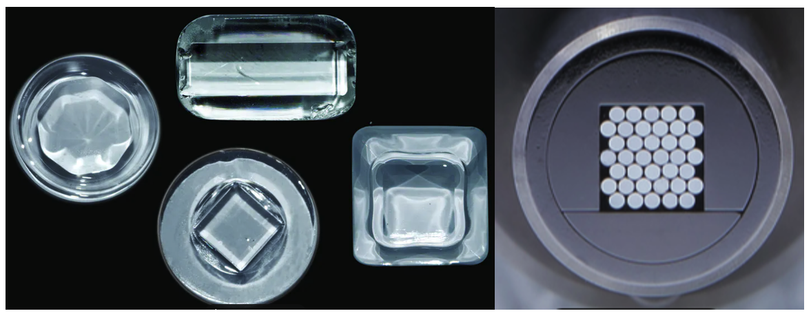
Newer silicon-shaped fiber cores are also now available in rectangular, square, octagonal, and hexagonal shapes (and more), providing more options and excellent coupling efficiencies. Armadillo SIA in Riga, Latvia is one supplier of these unique fiber-core geometries. Typically, round cladding is used with silica cores, so the fiber can work with round ferrules and standard optical connectors.
Armadillo also offers tapered fiber solutions and non-round fibers in singular cables that support many advanced applications. They usually use fluorinated silica cladding that conforms to the fused, non-circular core, mimicking its optical properties. Their angular fiber cores work well with diode laser devices.
Final thoughts
Data-center external DACs typically use round copper conductors, electrically matched to pluggable receptacles. These receptacles properly support the internal copper cable’s round conductors, which go from the IO faceplate to a switch or controller chip.
However, it’s expected that certain internal jump-over copper cable designs might change and use flat twin-axial conductors instead. This is particularly true as AOCs or AOMs pluggable options gain popularity over the DACs. CPO interconnects are already using various optical round-fiber assemblies to connect with faceplates and midplanes.
The round optical transmission format is ideal for applications, such as with the VCSEL, to ensure high-quality photonic transmission performance. The use of round optical fiber — externally and internally — has been key to achieving the top performance for RoCE, IB, FC, Slingshot, and other IO interface links when using pluggable types (such as SFP112, QSFP112, QSFP-DD112, and OSFP112).
Internal and round fiber-optical circuit boards will likely be used with more regularity in transmission modules, switches, servers, storage, persistent memory, and video grabbers.
At the same time, non-rounded core and fibers could prove useful for embedded computing and industrial network types/applications and market segments. As optics technology develops in addtional industries, such as the automotive sector, demand for unique or different fiber and core shapes will likely only grow.
