• Skip to primary navigation
  • Skip to main content
  • Skip to primary sidebar
  • Skip to footer

Electrical Engineering News and Products

Electronics Engineering Resources, Articles, Forums, Tear Down Videos and Technical Electronics How-To's

  • Products / Components
    • Analog ICs
    • Connectors
    • Microcontrollers
    • Power Electronics
    • Sensors
    • Test and Measurement
    • Wire / Cable
  • Applications
    • Automotive/Transportation
    • Industrial
    • IoT
    • Medical
    • Telecommunications
    • Wearables
    • Wireless
  • Resources
    • DesignFast
    • Digital Issues
    • Engineering Week
    • Oscilloscope Product Finder
    • Podcasts
    • Webinars / Digital Events
    • White Papers
    • Women in Engineering
  • Videos
    • Teschler’s Teardown Videos
    • EE Videos and Interviews
  • Learning Center
    • EE Classrooms
    • Design Guides
      • WiFi & the IOT Design Guide
      • Microcontrollers Design Guide
      • State of the Art Inductors Design Guide
    • FAQs
    • Ebooks / Tech Tips
  • EE Forums
    • EDABoard.com
    • Electro-Tech-Online.com
  • 5G

Write images and drill holes on flex circuits

December 7, 2020 By Martin Rowe

Orbotech’s Infinitum 10/10XT writes directly on flexible PCB resist to produce circuit images while the Apeiron system uses lasers to drill via holes.

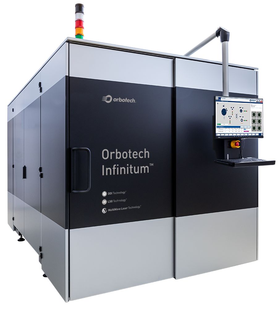
Infinitum uses pulsed lasers to directly write circuit race images on flex PCB resist.

With all the talk about 5G radios and wireline networks, it’s easy to forget that all the components either attach to or are connected by flexible and rigid printed-circuit boards (PCBs). Unless, of course, you’re responsible for designing or manufacturing those circuits. While rigid PCBs must be manufactured entirely on panels, flex circuits can be produced from rolls of copper. Orbotech has introduced two machines that use lasers to form circuit images and to “drill” via holes. Many of today’s circuits have lines too fine and spacings too small for traditional production methods.

When I was in high school, I worked afternoons for a manufacturer of flex circuits. Back then, flex circuits were “panelized” similar to rigid PCBs. Let’s assume a single-sided circuit for simplicity. The copper substrate had an insulating backing, and the exposed side would get coated with a photosensitive resist. A mask containing the circuit’s image would impose the image on the resist. An etching process would then remove the unwanted copper, leaving the circuit. When vias were needed, a drilling machine would drill them through several layers of the “panels” stacked up on each other.

Because today’s circuit are so much more complex than they were at that time and factory floor space much more expensive, flex circuits are now fabricated on rolls instead of sheets that were manually cut. Instead of shooting a circuit image into the copper’s photosensitive material, Orbotech’s Infinitum 10/10XT series uses a programmable laser to expose the photosensitive material at the proper locations. The video below shows how the Infinitum’s lasers operate as the copper rolls by, a process called “Drum Direct Imaging,” all within a 3.4 m × 2 m footprint.

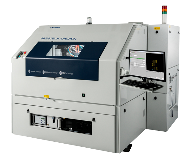
Apeiron uses lasers to drill holes in flex circuits.

The Infinitum can produce lines and spaces between them (line/space, L/S) at distance as small as 10 µm and 15 µm, respectively. It’s registration accuracy (feature-to-Grid, FTG) is ±10µm. Running for 24 hours, the Infinitum can write images on 2400 m to 2700 m of copper.

Flex circuits also need holes drilled in them that become vias for connecting traces through the material or for installing components. While the traditional way to do that was to align multiple sheets and drill through them, Orbotech’s Apeiron system “drills” holes through the PCB material using lasers. It uses mirrors to create four lasers from one source and directs them onto the roll or panel.

Each of the drilling lasers has a working area of 65 mm × 65 mm. It supports simultaneous drilling of two 260 mm sheets placed side-by-side. The machine’s precise measurement tools provide accurate drilling position while laser-beam monitoring tools ensure high drilling quality with optimal beam.

DesignFast Banner version: 03eceadf

Filed Under: 5G, Applications, PCB Design, Telecommunications Tagged With: Orbotech

Primary Sidebar

EE Training Center Classrooms

EE Classrooms

Featured Resources

  • EE World Online Learning Center
  • CUI Devices – CUI Insights Blog
  • EE Classroom: Power Delivery
  • EE Classroom: Building Automation
  • EE Classroom: Aerospace & Defense
  • EE Classroom: Grid Infrastructure
Search Millions of Parts from Thousands of Suppliers.

Search Now!
design fast globle

R&D World Podcasts

R&D 100 Episode 7
See More >

Current Digital Issue

April 2022 Special Edition: Internet of Things Handbook

How to turn off a smart meter the hard way Potential cyber attacks have a lot of people worried thanks to the recent conflict in Ukraine. So it might be appropriate to review what happened when cybersecurity fi rm FireEye’s Mandiant team demonstrated how to infiltrate the network of a North American utility. During this…

Digital Edition Back Issues

Sponsored Content

Positioning in 5G NR – A look at the technology and related test aspects

Radar, NFC, UV Sensors, and Weather Kits are Some of the New RAKwireless Products for IoT

5G Connectors: Enabling the global 5G vision

Control EMI with I-PEX ZenShield™ Connectors

Speed-up time-to-tapeout with the Aprisa digital place-and-route system and Solido Characterization Suite

Siemens Analogue IC Design Simulation Flow

More Sponsored Content >>

RSS Current EDABoard.com discussions

  • Smallest header needed to support PCB vertically above main PCB
  • What base emitter resistors are inside Darlington
  • Simulation of resonator in HFSS
  • series connection of power audio amplifier
  • Sampling with MOS transistor and cap

RSS Current Electro-Tech-Online.com Discussions

  • software PWM
  • ASM - Enhanced 16F and long calls - how?
  • Ampro 16mm Stylist projector woes.
  • Will Header and socket hold this PCB OK?
  • Passthrough charging-simple but impossible to achieve?

Oscilloscopes Product Finder

Footer

EE World Online

EE WORLD ONLINE NETWORK

  • 5G Technology World
  • Analog IC Tips
  • Battery Power Tips
  • Connector Tips
  • DesignFast
  • EDABoard Forums
  • Electro-Tech-Online Forums
  • Engineer's Garage
  • Microcontroller Tips
  • Power Electronic Tips
  • Sensor Tips
  • Test and Measurement Tips
  • Wire & Cable Tips

EE WORLD ONLINE

  • Subscribe to our newsletter
  • Lee's teardown videos
  • Advertise with us
  • Contact us
  • About Us
Follow us on TwitterAdd us on FacebookConnect with us on LinkedIn Follow us on YouTube Add us on Instagram

Copyright © 2022 · WTWH Media LLC and its licensors. All rights reserved.
The material on this site may not be reproduced, distributed, transmitted, cached or otherwise used, except with the prior written permission of WTWH Media.

Privacy Policy