• Skip to primary navigation
  • Skip to main content
  • Skip to primary sidebar
  • Skip to footer

Electrical Engineering News and Products

Electronics Engineering Resources, Articles, Forums, Tear Down Videos and Technical Electronics How-To's

  • Products / Components
    • Analog ICs
    • Connectors
    • Microcontrollers
    • Power Electronics
    • Sensors
    • Test and Measurement
    • Wire / Cable
  • Applications
    • Automotive/Transportation
    • Industrial
    • IoT
    • Medical
    • Telecommunications
    • Wearables
    • Wireless
  • Resources
    • DesignFast
    • Digital Issues
    • Engineering Week
    • Oscilloscope Product Finder
    • Podcasts
    • Webinars / Digital Events
    • White Papers
    • Women in Engineering
  • Videos
    • Teschler’s Teardown Videos
    • EE Videos and Interviews
  • Learning Center
    • EE Classrooms
    • Design Guides
      • WiFi & the IOT Design Guide
      • Microcontrollers Design Guide
      • State of the Art Inductors Design Guide
      • Power Electronics & Programmable Power
    • FAQs
    • Ebooks / Tech Tips
  • EE Forums
    • EDABoard.com
    • Electro-Tech-Online.com
  • 5G

How PAM4 moves bits through networks

May 27, 2022 By Martin Rowe

In an audio interview, Semtech’s Raza Khan explains why 5G networks use the four-level modulation to transport baseband data, starting at the radio.

measurementblues · EE World discusses PAM with Raza Khan

After a cellular radio demodulates signals that represent voice and data, the bits become baseband digital data streams. Those bits must travel through telecom networks, data centers, the internet, and the local networks of homes and businesses to reach the user. Until not long ago, serial data streams traveled through wires and fiber optics as simple two-level bits. As speeds increased, a funny thing happened. The signal became distorted to the point where receivers could no longer distinguish a digital one from a digital zero. Bandwidth in electrical signals and dispersion in optical signals took their toll.

Along came signal conditioning and predistortion, which compensated for losses — to a point. Simple modulation was no longer enough.

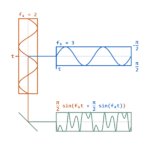
Enter complex digital modulation. Instead of sending one bit at a time using two amplitudes — called non-return-to zero (NRZ) — networks and the standards that drive them began using two bits per symbol instead of one. Four-level pulse-amplitude modulation (PAM4), which uses four levels with each level representing two bits, provided a way to double the data rate without doubling the symbol (baud) rate. The figure shows an eye diagram of a PAM4 signal. An eye diagram is an overlay of many symbols viewed on an oscilloscope. When you get enough symbols, you get an opening that looks like an eye, assuming the signal has sufficient integrity.

PAM4 modulation

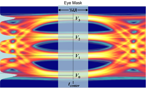
A PAM4 signal uses four amplitude levels with each representing two bits.

All signals face degradation when traveling over fiber or copper. The degradations are, however, different. In the audio discussion, Raza Khan of Semtech covers how signals degrade in optical transmission as they pass through fiber. He looks at dispersion, the “stretching” of optical signals than can cause symbols to overlap, making the receiver’s job more difficult or even impossible. Dispersion limits a fiber connection’s reach.

Khan also explains the difference in terminology between the electrical and optical community. Simply put, optical links aggregate several electrical links. For example, a 400G (400 Gb/sec) optical link might consist of data from eight 56 Gb/sec electrical links, which comes from eight 28 Gbaud PAM4 signals. The electrical community tends to use data rates such as 28, 56, and 112 Gb/sec, which include framing overhead. The optical community uses numbers such as 25G, 50G, 100G, and so on.

In the interview, Khan also discusses issues with having a four-level symbol as opposed to two levels. For example, the eye diagram in the figure shows a symmetrical middle eye as compared to the upper and lower eyes. That difference has to do with rise and fall arrival times, the time it takes for an edge to cover the different levels.

Because of the three eyes, PAM4 uses a different set of measurements, called TDECQ, than used for NRZ signals. The traditional eye-mask measurements no longer apply.

Listen to the discussion, but keep your eye on a PAM4 signal’s three eyes.

You may also like:


  • The up side of under sampling

  • Coherent optics move toward interoperability

  • The difference between signal under-sampling, aliasing, and folding

  • How coherent optics increase data rates

  • How PCIe interface developments have changed and advanced

Filed Under: 5G, Applications, FAQ, Featured, Telecommunications, Wireless Tagged With: semtech

Primary Sidebar

EE Training Center Classrooms.

EE Classrooms

Featured Resources

  • EE World Online Learning Center
  • RF Testing Basics
  • Power Supply Fundamentals
  • Women in Engineering
  • R&D 100 Podcast
Search Millions of Parts from Thousands of Suppliers.

Search Now!
design fast globle

R&D World Podcasts

R&D 100 Episode 8
See More >

Current Digital Issue

June 2022 Special Edition: Test & Measurement Handbook

A frequency you can count on There are few constants in life, but what few there are might include death, taxes, and a U.S. grid frequency that doesn’t vary by more than ±0.5 Hz. However, the certainty of the grid frequency is coming into question, thanks to the rising percentage of renewable energy sources that…

Digital Edition Back Issues

Sponsored Content

New Enterprise Solutions for 112 Gbps PAM4 Applications in Development from I-PEX

Positioning in 5G NR – A look at the technology and related test aspects

Radar, NFC, UV Sensors, and Weather Kits are Some of the New RAKwireless Products for IoT

5G Connectors: Enabling the global 5G vision

Control EMI with I-PEX ZenShield™ Connectors

Speed-up time-to-tapeout with the Aprisa digital place-and-route system and Solido Characterization Suite

More Sponsored Content >>

RSS Current EDABoard.com discussions

  • Why don't 2 flip-flop synchronizers have a reset?
  • Electrical wire sizing
  • Help designing 1.6KW Isolated AC/DC with Constant Current Output
  • understanding the logic of class object name repeats twice question
  • [Moved]PySpark Training in Bangalore Marathahalli _ Dvs Technologies

RSS Current Electro-Tech-Online.com Discussions

  • Bose SoundTouch 20 - IC identification
  • CE Transistor Amplifier
  • arduino help needed
  • SIMON game with more umph!
  • Washing Machine motor

Oscilloscopes Product Finder

Footer

EE World Online

EE WORLD ONLINE NETWORK

  • 5G Technology World
  • Analog IC Tips
  • Battery Power Tips
  • Connector Tips
  • DesignFast
  • EDABoard Forums
  • Electro-Tech-Online Forums
  • Engineer's Garage
  • Microcontroller Tips
  • Power Electronic Tips
  • Sensor Tips
  • Test and Measurement Tips
  • Wire & Cable Tips

EE WORLD ONLINE

  • Subscribe to our newsletter
  • Lee's teardown videos
  • Advertise with us
  • Contact us
  • About Us
Follow us on TwitterAdd us on FacebookConnect with us on LinkedIn Follow us on YouTube Add us on Instagram

Copyright © 2022 · WTWH Media LLC and its licensors. All rights reserved.
The material on this site may not be reproduced, distributed, transmitted, cached or otherwise used, except with the prior written permission of WTWH Media.

Privacy Policy