
One of the first things EE students learn in their ac circuits course is resonance. Electrical resonance, to quickly review, arises in an electric circuit at a frequency called the resonances frequency when the impedances or admittances of circuit elements cancel each other. In some circuits, resonance happens when the impedance between the input and output of the circuit is almost zero and the transfer function is close to one.
Of course, resonance can also arise in mechanical vibration scenarios and other natural settings. Perhaps one of the more interesting natural phenomenon involving resonance is tidal resonance at the Bay of Fundy. Here coastal waters exhibit one of the resonant modes of the ocean. Ocean resonance effects are most apparent when a continental shelf is a quarter of a wavelength wide. A tidal wave is then reinforced by reflections between the coast and shelf edge. The result is a much higher tidal range. The speed of ocean waves is equal to the square root g x h, where g is the acceleration of gravity and h is the depth of the ocean. For a continental shelf having a depth of 100 m, the speed is about 30 m/sec. So if the tidal period is 12 hours, a quarter-wavelength shelf will have a width of approximately 300 km.
It’s easy to calculate the resonance frequency of ordinary components and circuits. An LC circuit resonates when driven at a frequency at which the inductive and capacitive reactances are equal in magnitude. This resonant frequency is ω=1/√LC, where L is the inductance in Henries and C is the capacitance in Farads. The angular frequency, ω, has units of radians per second. The equivalent frequency in units of hertz is f = ω/2π = (1/2π) × √LC.
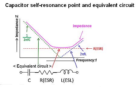
Capacitor behavior at the self-resonance point and a commonly used equivalent circuit as depicted by Panasonic Industrial.
The problem with calculating a component or circuit resonance is that the equations typically assume ideal components. The reality is more complicated. For example, capacitors obey the classic capacitive reactance equation Xc=1/2πfC only up to a certain frequency, usually specified in the data sheet, at which point they self resonate because of parasitic inductive elements within their internal construction. At that point Xc dips to zero because the parasitic inductive reactance equals the capacitive reactance. There are analogous effects for inductors and even ordinary resistors.
To complicate matters a bit more, the self resonant frequency given in data sheets assumes external conditions that may not represent those of the actual circuit. In leaded capacitors, for example, the data-sheet self-resonance frequency typically assumes a relatively short lead length. If the real leads are longer, the parasitic inductance rises, lowering the self-resonant frequency.
The realities of non-ideal components can also affect resonating entities that are not circuits or electronic components. Piezoelectric transducers for power ultrasonics are an example. Most of these are of the Langevin type where one or more piezoceramics are mechanically compressed (prestressed) between a front and back driver. Schematically, these piezo transducers appear as series-resonant L-C circuits. Electrodes on either side of the piezo plate form a capacitor, and the resonating mass acts as an inductance. The exact resonant frequency of the transducer depends somewhat on the environment in which it vibrates. Driving the transducer at its resonant frequency maximizes the power transfer from the transducer into the media in which it works.
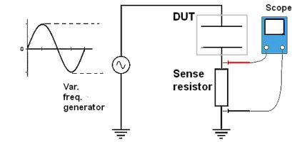
Simple measurement setup for viewing the resonance of a DUT.
In such cases, it may be more accurate to measure the resonant frequency rather than calculate it. The simple way of testing for the resonance frequency is to apply a signal generator to the DUT while monitoring the voltage across it with an oscilloscope. Sweeping the frequency upward while monitoring the voltage across the device should produce a scope display of voltage that hits a minimum at the resonance point of the DUT, indicating the point at which reactance is at a minimum. It may take some rocking of the generator frequency back and forth to determine the voltage minimum.
Also note it is a good practice to insert a resistance in series between the signal generator output and the resonant circuit. The point of this practice to prevent the signal generator from directly driving a circuit having essentially zero resistance, i.e. a short circuit, at the resonance point. Generally speaking, it is not a good idea to put a short circuit on the output of a signal source, though it may not matter much for low-level signals.
Additionally, a resistor in series with the DUT can serve as a sense resistor when it is impractical to put scope probes across the DUT. Again taking an ultrasonic piezo transducer as an example, current through the transducer depends on its impedance, which in turn depends on the driving frequency. The voltage drop across a sense resistor in series with the transducer will indicate the amount of current through the transducer. At resonance, the impedance of the transducer is minimum and maximum current flows. This same current causes a voltage drop in the sense resistor, and the maximum current (at resonance) will show the maximum voltage.