
by Travis Thurman, Chief Design Engineer, TDK
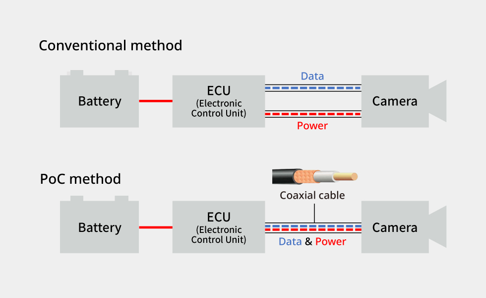
Modern vehicles face a critical infrastructure challenge: efficiently delivering both power and high-speed data to dozens of cameras, sensors, and electronic systems without creating a tangled web of heavy, interference-prone wiring. As Advanced Driver-Assistance Systems (ADAS) and autonomous capabilities expand, traditional separate-cable approaches are reaching their practical limits. Power over Coaxial (PoC) technology offers automotive designers a practical solution by consolidating power and data transmission into a single coaxial cable.
Escalating cable count and weight
Today’s vehicles integrate 8 to 12 cameras for surround-view systems, parking assistance, and lane monitoring, plus additional sensors for adaptive cruise control, blind-spot detection, and collision avoidance. Each component traditionally required separate power and data cables, creating wire harnesses that can weigh 40 to 60 kg in modern vehicles or approximately 3-4% of total vehicle weight.
Traditional wiring approaches create several cascading problems: the physical bulk of separate cables complicates routing through tight spaces near A-pillars, door frames, and bumpers; increased copper usage raises material costs and vehicle weight; and more cables mean more connection points, each of which can represent a potential failure mode.
EMI challenges
Automotive electromagnetic environments are hostile. High-current systems such as electric power steering, seat motors, and electric drivetrains generate significant EMI across broad frequency spectrums. The problem intensifies with data rates. Early automotive cameras operated at 100 Mbps, but current high-definition systems require 1.5 to 3 Gbps, with emerging 4K cameras pushing toward 6 to 12 Gbps. At these frequencies, even minor EMI can corrupt data packets, requiring retransmissions and introducing latency that is unacceptable for safety-critical ADAS functions, where response times must stay below 100 milliseconds.
Architecture and signal separation
PoC technology uses frequency-domain multiplexing to simultaneously transmit dc power and high-frequency data over a single 50 Ω or 75 Ω coaxial cable. The dc power component (typically 12V or 24V automotive bus voltage) occupies the 0 Hz to approximately 10 kHz range. At the same time, serialized video data operates in the 10 MHz to 3 GHz spectrum, depending on the protocol (FPD-Link III, GMSL2, or similar).
The physical separation occurs through filter networks at both ends. At the source, an LC filter with a corner frequency around 100 kHz couples dc power onto the coax center conductor while blocking high-frequency data from entering the power supply. At the load end, a complementary filter extracts dc power and routes high-frequency signals to the deserializer or camera image processor.
Comparison: traditional vs. PoC wiring
Consider a typical rear-view camera installation. Traditional implementation requires a two-conductor power cable (16-18 AWG, ~45 g/m) and a shielded twisted-pair data cable (~35 g/m), for a total of ~80 g/m, plus separate connectors. PoC implementation uses a single RG-174 or RG-179 coaxial cable (~30 g/m) with one connector.
For a 4m cable run, this represents a weight reduction of approximately 200 grams per camera or 2.4 kg saved across 12 cameras. In electric vehicles, where every kilogram affects range, this contributes measurably to efficiency targets.
Filter design requirements
Effective PoC filters must maintain the coaxial cable’s characteristic impedance (50Ω or 75Ω) across the data signal bandwidth while providing high impedance to dc power and low impedance to high-frequency data at the power coupling point. This requires inductors with dc resistance typically 50-200 mΩ to minimize power loss, a self-resonant frequency above 3 GHz to avoid attenuation in the data band, impedance flatness of ±15% from 10 MHz to 3 GHz, and current ratings of 500 mA to 2 A depending on camera/sensor power requirements.
Traditional wire-wound inductors struggle to meet these specifications simultaneously. Single-winding designs often exhibit impedance peaks and valleys across the frequency range due to parasitic capacitance between windings and core losses at high frequencies.
Bifilar winding innovation
Bifilar winding, which uses two parallel conductors wound simultaneously on a common core, addresses impedance stability by reducing parasitic effects and lowering dc resistance through parallel current paths while maintaining high inductance. According to TDK engineers, bifilar-wound inductors can maintain impedance within ±10% from 10 MHz to 6 GHz, compared to ±25% variation in conventional designs. The parallel-winding structure also improves current handling: where single-winding 0805-package inductors might handle a maximum of 500 mA, bifilar designs in the same footprint can handle 1 A or more.
Thermal and environmental considerations
Automotive PoC systems must operate reliably over the temperature range of -40°C to +150°C. At temperature extremes, inductor performance can degrade significantly as core materials shift magnetic properties and copper windings experience resistance changes of approximately 0.4% per degree Celsius.
Modern automotive-grade inductors use temperature-stable ferrite compositions with Curie temperatures above 200°C and specify inductance tolerance of ±20% across the full operating range. For PoC applications, this stability is critical. A 30% inductance shift could shift the filter corner frequency enough to either attenuate data signals or fail to block them from the power supply. Component miniaturization presents additional thermal challenges requiring attention to PCB copper pour for heat spreading and thermal vias to transfer heat to ground planes.
EMI mitigation through coaxial topology
Coaxial cable’s inherent structure provides superior EMI immunity compared to twisted-pair alternatives. The outer conductor shields the center conductor from external electromagnetic fields, with effectiveness typically exceeding 80 dB from 10 MHz to 1 GHz for quality automotive-grade cable. In EMI testing, PoC implementations typically exhibit radiated emissions 20-30 dB lower than those of unshielded twisted-pair solutions, making compliance with CISPR 25 Class 5 limits significantly easier.
The combination of shielded transmission and integrated power delivery eliminates ground loops that often plague separate power/data systems. In a PoC, the coax shield serves as the signal return path, and proper single-point grounding at the ECU end prevents circulating currents that can induce common-mode noise.
Design considerations and trade-offs
PoC’s primary limitation is power delivery capacity. RG-174 coax with 20 AWG center conductor has dc resistance of around 32 Ω/km. For a 5-meter run at 1 A, that’s 160 mV drop and 160 mW dissipation in the cable alone. For cameras requiring 12V ±5% at the module, this limits practical current to approximately 1.5 A over 5 meters. High-power devices like lidar sensors (10-20 W) remain better suited to separate power feeds, while PoC excels for individual cameras drawing 1-5 W, radar sensors at 2-3 W, and ultrasonic sensors under 1 W.
Connector selection
Automotive PoC implementations typically use FAKRA coaxial connectors (standardized per IEC 60169-43) or miniaturized coax connectors meeting USCAR-2 specifications. FAKRA connectors include mechanical keying and color coding to prevent mis-mating. The connector must maintain 50 Ω impedance along its length and provide secure mechanical retention through vehicle vibration (per ISO 16750-3, up to 50g shock), with contact resistance under 10 mΩ.
Implementation guidelines
Cable routing: Maintain a minimum 50mm separation from high-current power cables. While coax provides excellent shielding, extremely strong fields can still induce noise.
Filter placement: Position power coupling filters as close as possible to connectors to minimize stub lengths. An unterminated 25mm stub can create reflections affecting signals above 2 GHz.
Ground management: Establish a single-point ground at the ECU end. Multiple ground connections create potential difference paths that couple noise onto the shield.
Component selection: Verify inductor and capacitor ratings for AEC-Q200 compliance, particularly for moisture sensitivity level and temperature cycling from -40°C to +125°C.
Testing strategy: Use S-parameter analysis to characterize filter insertion loss, return loss, and group delay across the full data bandwidth. Target specifications: insertion loss < 1 dB, return loss > 15 dB from 10 MHz to 3 GHz.
Future developments
Next-generation systems will need to support 8K cameras (48 Gbps) and emerging lidar-on-chip sensors, pushing coaxial transmission to 10 GHz and beyond. Simultaneously, smart cameras with integrated neural network processors may consume 10-15 watts, approaching the practical limits of single-coax power delivery. Research into active voltage regulation at the camera end and higher-voltage power distribution (24V or 48V) aims to extend PoC viability to these higher-power applications.
The ultimate goal remains unchanged: simplifying vehicle electrical architecture while improving reliability and reducing weight. PoC technology, supported by continuous innovations in passive components, offers automotive designers a proven path toward that objective.