
By Fernando Auñón, Fernando Rodríguez, Sergio Sepúlveda, David Olalla
TDK Electronics
For engineers to predict the real-world performance of film capacitors, it’s crucial to understand the electromagnetic and thermal behavior of film capacitors that serve as DC links, filters, and energy buffers. The precision of the design in power electronics determines performance, reliability, and cost. Systems are becoming more compact and efficient thanks to wide-bandgap semiconductors and higher switching frequencies, but every component must be optimized to operate at the limits of electrical and thermal capability.
With web-based simulation tools and validated digital models, engineers can get quick and reliable insights into the electrical and thermal behavior of components and subsystems before building a prototype and performing hardware tests. These tools give designers accurate digital representations of film capacitors and allow them to size, select, and integrate components with confidence.
The principles of Digital Twin testing
With digital twins (virtual replicas of objects or systems) of capacitors, engineers can simulate system-level interactions such as current density, self-heating, and electromagnetic coupling. This greatly reduces prototyping effort and increases confidence in performance predictions.
Three core principles can help ensure digital twins build accurate models:
- Representative testing: To ensure repeatable data, samples from each product series undergo electromagnetic and/or thermal characterization under controlled conditions.
- Simulation validation: Under identical boundary conditions, finite element simulations are conducted. These results are then compared with measured data, tuning models until they match closely with measurements.
- Series modeling: Validated model parameters are generalized to represent the entire capacitor series under a range of operating conditions.
This workflow makes sure each digital model accurately reproduces real-world capacitor behavior for both system-level and component-level simulations. Let’s look at the types of modeling needed for capacitor digital twins.
Electromagnetic modeling
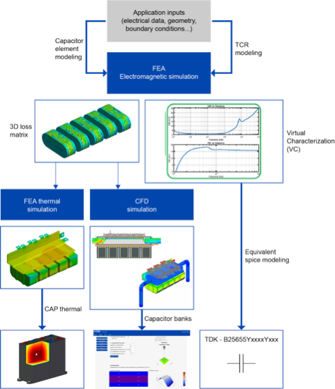
Electromagnetic (EM) modeling enables engineers to virtually analyze electric fields, current paths, and parasitic effects within the capacitor structure, providing information that cannot be fully captured by measurement alone. The modeling begins with input data like geometry, materials, and boundary conditions (e.g., applied voltage, current, and ambient temperature), all used to perform detailed 3D EM simulations.
The output of these simulations includes the loss distribution matrix (a 3D map of internal losses) and key electrical characteristics, such as impedance magnitude |Z|, capacitance (C), equivalent series resistance (ESR), and equivalent series inductance (ESL). The resulting virtual characterization is an electrical fingerprint of the capacitor and serves as the foundation for SPICE (an open-source analog electronic circuit simulator) and thermal models.
EM simulation data reproduces all measurable electrical parameters of a capacitor to produce a virtual characterization. This includes frequency-dependent curves for ESR, ESL, and capacitance and allows engineers to evaluate performance across operating conditions.
Virtual characterization can extract parameters without physical samples, which greatly accelerates the design process. It also allows engineers to evaluate the effects of manufacturing tolerances and end-of-life (EOL) conditions, including changes in film thickness, metallization resistance, and dielectric aging, before building a prototype of their system. This helps designers ensure stable system behavior throughout their product’s lifetime.
Understanding electromagnetic effects
Beyond determining electrical parameters, EM modeling reveals internal electromagnetic interactions that affect the performance and reliability of the component. Through simulation, engineers can visualize effects like inhomogeneous impedance distribution caused by asymmetrical current paths, skin and proximity effects at high frequencies, and internal resonances within the capacitor structure. Recognizing such effects helps engineers refine designs and avoid resonant stress during operation.
Thermal modeling
Thermal modeling shows how those losses translate into temperature rise, a critical factor in capacitor lifetime. The thermal behavior is largely determined by how the internal resistance of the component changes with temperature, described by the thermal coefficient of resistance (TCR).
TCR values are well documented for bulk metals, but metalized films, used in film capacitors, exhibit distinct properties due to their microstructure and thickness. TCR significantly influences the temperature-dependent ESR, which directly affects losses and hotspot formation. By including TCR data in simulations, designers can predict how ESR and temperature rise evolve.
Thermal modeling follows the same validation philosophy (test, simulate, and then model) as EM modeling. Representative samples are instrumented with thermocouples and tested under well-defined load conditions, and the results are compared to 3D finite element thermal simulations. Then the models are adjusted until the temperature distribution and hotspot predictions align within a narrow tolerance.
Validated thermal models serve as the foundation for web-based design tools that estimate temperature rise in capacitor arrays and calculate internal thermal profiles for individual capacitors, bridging the gap between detailed finite element analysis and practical engineering use.
Benefits of thermal modeling
Accurate thermal modeling provides early lifetime estimation based on hotspot temperature and helps engineers select optimal cooling strategies for PCB or system-level design. It also helps reduce over-dimensioning, saving space and cost, and allows faster design iterations with fewer prototype tests.
When combined with EM modeling, thermal simulations form a comprehensive digital representation of the capacitor’s physical behavior.
SPICE-Equivalent modeling
SPICE simulation remains one of the most powerful tools for predicting circuit behavior for engineers designing converters or inverters, but the accuracy of SPICE results depends on precise component modeling. Real capacitors exhibit frequency-dependent impedance and loss characteristics that aren’t captured by a single ideal capacitor element. This makes SPICE-equivalent models that replicate the measured electrical behavior of real capacitors across both time and frequency domains essential.
These models are derived directly from electromagnetic simulations and validated test data in which a network of passive elements — such as resistors, capacitors, and inductors — may be arranged to reproduce the same impedance response as the physical device.
Striking an accuracy and computation balance
Practical SPICE models must balance accuracy and computation time. More circuit elements yield higher fidelity but increase the computational load. This makes it necessary to optimize the number of components to maintain precision while remaining simulation-efficient.
For both single components and subsystems
The same methodology can be applied to modeling complete capacitor assemblies and elements at the component level. Engineers can create SPICE representations of multi-capacitor DC links, PCB-mounted banks, or even entire converter subsystems, including busbar inductances and parasitic couplings.
Electromagnetic interactions and design insights
Electromagnetic modeling also provides unique insights into how energy and current distribute within a capacitor, which is crucial when designing compact high-current systems where local resonances and parasitic couplings can cause significant performance degradation. EM simulation enables visualization of effects like internal resonances, inhomogeneous current paths, and local field concentrations. Designers can adjust internal geometry, terminal layout, or metallization patterns to mitigate stress and improve long-term reliability if these effects are detected early enough.
Thermal integration for components and subsystems
In modern applications like automotive and renewable-energy systems, capacitors operate in close thermal interaction with semiconductors, busbars, and cooling structures. Evaluating the capacitor in isolation no longer suffices. To provide a more accurate picture of how heat is transferred and dissipated in the real system, thermal simulation is extended beyond the individual component to include the entire local subsystem (the DC-link capacitor, semiconductor modules, and cooling unit).
Thermal integration modeling helps engineers optimize subsystem layout, improving cooling efficiency without oversizing components. It also helps avoid thermal bottlenecks to ensure even temperature distribution across modules. It can enable simultaneous electrical-thermal optimization by correlating electrical losses and heat flow, as well as reducing prototyping cycles with early simulations that deliver trustworthy performance estimates.
In automotive environments where every degree of temperature margin counts, for example, integrations like this can make the difference between meeting lifetime targets and early degradation.
Turning components into digital resources
Transforming standard film capacitor series into a simulation-ready digital resource can bridge the gap between laboratory testing and real-world application modeling. Merging electromagnetic, SPICE, and thermal modeling into a single accessible ecosystem — as seen, for example, in TDK’s CLARA platform — enables engineers to perform comprehensive analyses early in the design phase. This can reduce design iteration time through accurate pre-simulation, improve system reliability, optimize capacitor utilization by avoiding unnecessary oversizing, and enhance comparability between standard and customized solutions.
Designing high-performance power electronic systems requires a deep understanding of component behavior electrically, thermally, and in interaction with the surrounding system. Integrating electromagnetic, thermal, and SPICE techniques into simulation platforms brings more practical understanding into the digital domain, reducing design iteration time, minimizing prototype costs, and giving engineers greater confidence throughout the design process.