
Rohde & Schwarz recently announced their MXO3 1 GHz bandwidth 12-bit oscilloscope [1], and I managed to get one to review. The R&S MXO38 is ideal for EMC troubleshooting and characterizing design issues early. The 1 mV low noise vertical sensitivity, 12-bits, allows a terrific FFT spectrum display. The waveform capture is an amazing 4.5 million waveforms per second, providing real-time capture of up to 99%. From an EMC point of view, this provides a nearly real-time spectrum capture.
In this article, I’ll show you how I make a quick measurement of cable shielding effectiveness for coaxial cables using the R&S MXO38 oscilloscope. This is important because poorly shielded coax cables, when attached to your equipment under test, can cause radiated emission failures.
The measurement test setup is shown in Figure 1, where I’m injecting strong 100 MHz harmonic combs via an RF current probe clamped around the cable or cables. The MXO3 can display up to four spectral plots simultaneously, as shown in the figure; however, for accuracy, I’ll test each cable separately.
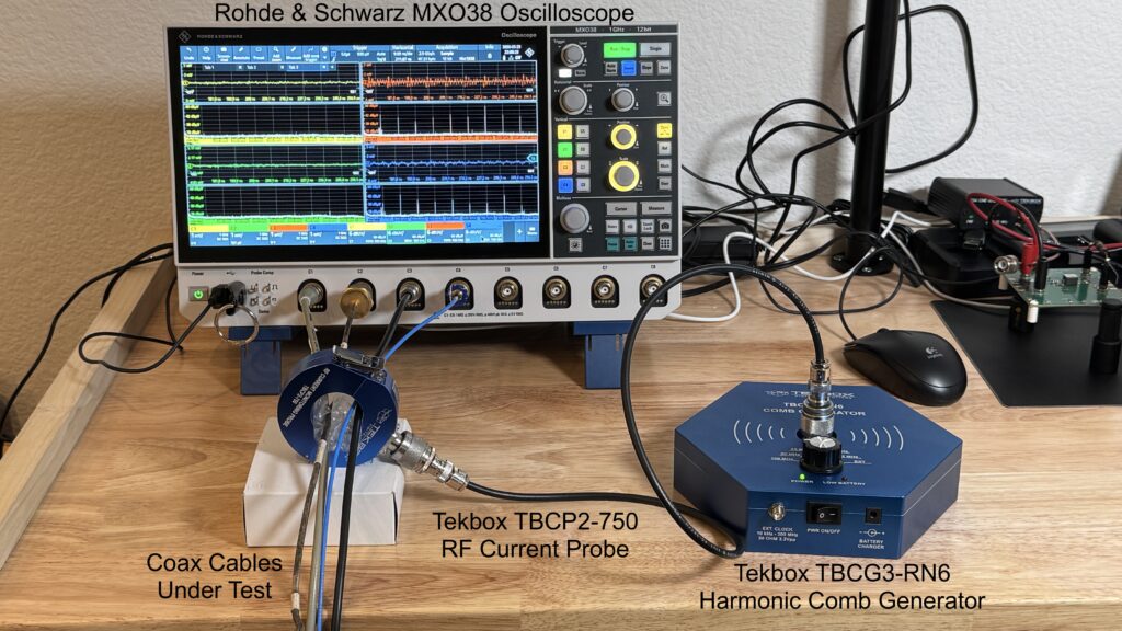
I’m using the Tekbox TBCG3-RN6 harmonic comb generator [2], which creates harmonics out to 6 GHz at 10, 25, 50, and 100 MHz combs. I elected to use 100 MHz combs to keep the data set reasonable.
These harmonic combs are injected into a Tekbox TBCP2-750 RF current probe [3], which is coupled to the cable or cables to be characterized.
Shielding effectiveness measurement
In order to characterize the shielding effectiveness of the coax cable shield, I’ll compare the resulting comb amplitude versus frequency of the shielded cable with the coupling to a single unshielded wire and then take the difference in readings according to the formula shown.
Shielding Effectiveness (SE) in dBµV = Vwire(dBµV) – Vcable(dBµV)
The MXO38 was configured to 50Ω input on Channel 1. The Spectrum Analyzer was turned on, and Start/Stop frequency was set to 1 MHz and 1 GHz, respectively, and Resolution BW set to 100 kHz. I used Max Hold to steady the resulting amplitudes. I used Autoset to achieve a usable display of the time domain.
All cables under test were approximately 3 feet in length and were terminated with a good 50Ω load. I’ll test each cable separately.
Calibration
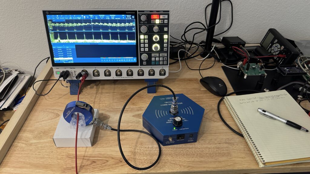
To establish a baseline measurement, I injected the combs into a single unshielded wire connected via a Pomona BNC-Banana Plug adapter connected to Channel 1 (Figure 2). We’ll assume this is the maximum coupling at each of the 100 MHz combs. These baseline data were recorded.
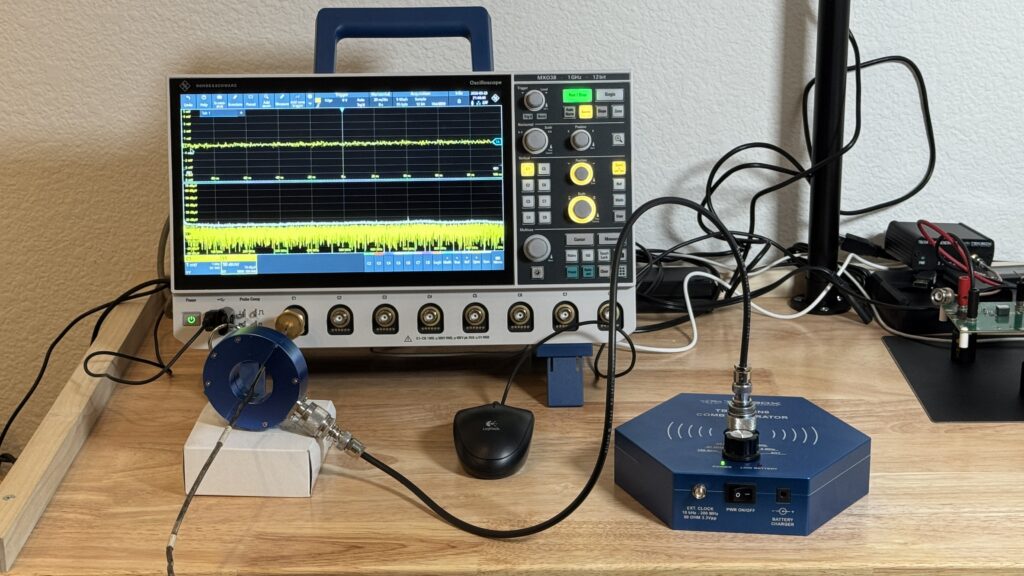
Next, I connected a length of semi-rigid coax to demonstrate the optimum shielding. To no surprise, I did not detect any combs coupling inside the coax (Figure 3). This confirmed the test setup was performing as expected.
Cable measurements
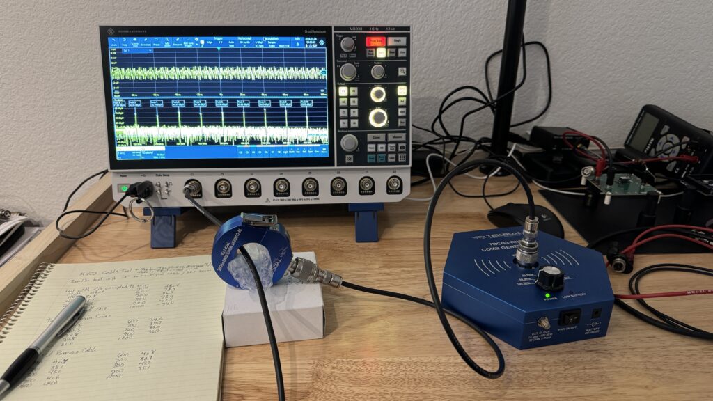
Next, I measured each cable under test, comparing several different types and general qualities. The amplitudes versus frequency data were recorded for each. Figure 4 shows the measurement of a standard Pomona 3-foot cable. Altogether, six cables were tested.
| Cable | Description |
| Aaronia | Good quality German RG316-type |
| Amazon | Generic RG316-type, unbranded, unknown quality |
| Beehive | Good quality RG316-type, used for near field probes |
| Gore | Very old, when new was excellent quality |
| HP | 30-year-old model 8120-1840 RG58-type |
| Pomona | Standard quality RG58-type |
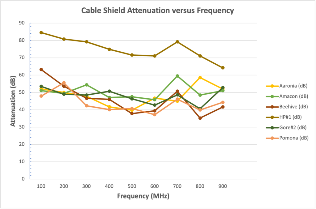
Results
The results were surprising. I expected the RG316-type cables to be among the best, but it seems all the cables seemed fairly bunched together up to about 600 MHz. After that, they seemed to differentiate more.
The Aaronia and Amazon cables generally had better SE above 600 MHz. The biggest surprise, though, was the HP cable, which was at least 30 years old and had seen a lot of use over the years.
The comb amplitude for the HP cable was either buried in the noise floor or was just visible above the noise floor. I tried a second HP cable with the same results. Even when testing the four cables simultaneously in Figure 1, you cannot observe any harmonic combs (upper left quadrant). I did notice these cables were not as flexible as the others (the Gore cable being the exception).
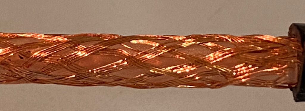
Dissection of the cables
While I really hated the thought of opening up one end of my excellent HP cable, I really did want to understand why it measured 20 dB higher SE and decided to compare it with the standard Pomona cable. Figure 6 shows the difference in weave and termination.
Both cable shields are terminated in a 360-degree bond to the connector ground shell. The HP appeared to be crimped as well as soldered. The Pomona used a conventional BNC connector where the shield was clamped all around with a threaded nut.

While the Pomona cable performed as well as most others, the best I could tell was that the HP cable had a tighter weave with very few gaps. Gaps are readily observed in the Pomona cable shield.
This is not the worst I’ve seen. I had purchased a generic unbranded coax cable from Amazon many years ago. Figures 7 and 8 show close-ups of the shield termination and weave. While fairly short, the cable shield termination was a soldered pigtail, which is not nearly as good as a 360-degree bond. Looking at a closer view of the weave (Figure 8) shows one of the loosest weaves I’ve ever seen, with large gaps throughout. Note that this cable was “very flexible”.

Summary
Poorly shielded cables used for radiated emissions compliance testing can be quite risky and usually lead to emissions failures. Quick characterization tests, such as the simple shielding test using a harmonic comb generator and RF current probe, can provide a quick check on the shielding quality and connector bonding of proposed test cables.
With its fast acquisition update rate, the MXO38 spectrum feature works extremely well for general bench-top EMC troubleshooting and debug, and it’s become one of my favorite bench-top tools [4 and 5]. The ease of setting up the analyzer is a step ahead of other leading manufacturers.
References
[1] Rohde & Schwarz[2] Tekbox comb generators
[3] Tekbox current probe
[4] Wyatt, R&S MXO3 Oscilloscope for EMC measurements: part 1
[5] Wyatt, R&S MXO3 Oscilloscope for EMC measurements: part 2