
Thermal interface materials (TIMs), adhesives, and sealants operate within fundamentally different constraints in electric vehicles (EVs) and high-power charging infrastructure.
In EVs, TIMs manage intermittent thermal loads under severe vibration and strict weight limits while meeting automotive qualification standards. In EV charging stations, they dissipate sustained thermal loads, withstand direct outdoor exposure, and maintain structural and sealing integrity over long service intervals.
This article compares TIM requirements in EVs and EV charging infrastructure, from duty cycle and thermal loading to environmental exposure and mechanical constraints.
Heat generation and TIM selection in charging infrastructure
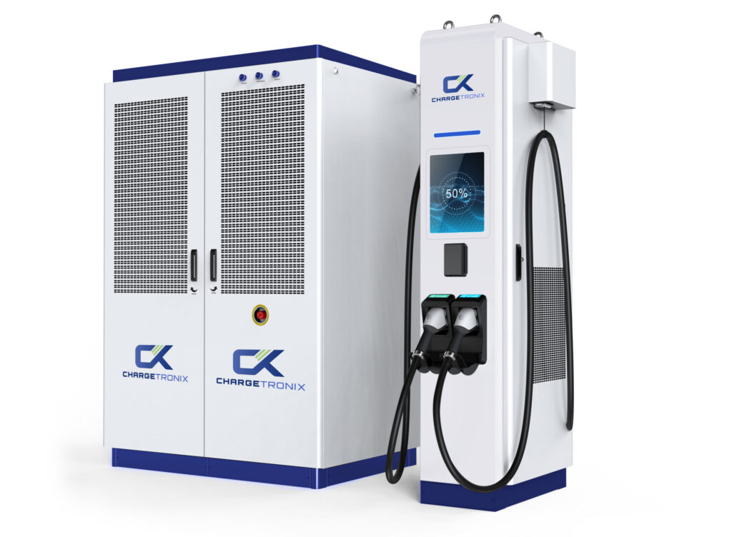
DC fast and ultra-fast EV chargers operate from 400 V to over 1,000 V and deliver more than 350 kW. As shown in Figure 1, distributed charger architectures enable these power levels by supplying multiple charging outputs from a shared power cabinet.
The dominant heat source is the insulated-gate bipolar transistor (IGBT), whose per-unit dissipation has increased from roughly 1.2 kW to 12.5 kW over the past three decades.
Within these high-power modules, TIM layers can account for up to 50% of total thermal resistance, directly determining junction temperature. An improperly specified interface can raise junction temperature by several degrees Celsius, forcing derating or reducing module life.
Charger designers select TIM formats according to subsystem demands and interface geometry. In high-power modules, for example, phase change materials flow at defined transition temperatures, form thin bond lines, and resist pump-out to maintain stable contact under compression.
At device-to-sink interfaces, high-conductivity gap pads provide robust thermal transfer, with conductivities reaching 8.3 W/m·K. On controller PCBs, dispensable silicone gels conform to narrow gaps and vertical surfaces, while dielectric insulator pads combine thermal transfer with electrical isolation where required.
Beyond the interface layer, cooling architecture scales with power density. Systems below 150 kW may rely on forced-air cooling with heat sinks. Above 150 kW, junction temperatures can exceed 200°C during fast-charge sessions, limiting air cooling effectiveness. High-power and ultra-fast chargers instead use liquid cooling, with TIMs forming the thermal interface between semiconductor junctions and cold plates or heat exchangers.
Environmental sealing and structural adhesives
Charging stations must safely operate in rain, snow, dust, UV radiation, salt spray, and wide ambient temperature swings. Enclosures typically carry IP65 or IP66 ratings, with IP67 required where temporary submersion is possible. Coastal or industrial installations may also require NEMA 4X corrosion protection. Achieving these protection levels depends on coordinated adhesive and sealing systems across each enclosure interface.
At the enclosure perimeter, conductive elastomer gaskets provide moisture sealing and EMI shielding, while silicone and polyurethane foams prevent dust and water ingress under prolonged UV exposure. Structural adhesives secure tempered glass, polycarbonate, or acrylic panels to accommodate thermal cycling and weathering.
At the board level, UV-curing conformal coatings limit abrasion and humidity ingress, and epoxy potting compounds encapsulate sensitive assemblies. Anaerobic threadlockers rated to 230°C maintain fastener retention without eliminating serviceability.
Material chemistry varies according to application requirements. Silicone systems address applications demanding flexibility, dielectric strength, UV stability, and temperature capability from −60°C to above 200°C.
Epoxies are used where shear strength, flame retardance, and corrosion resistance determine structural reliability. UV-curable materials support PCB protection through rapid cure and uniform conformal coating coverage, while toughened acrylics reinforce plastic housing assemblies where impact resistance is critical.
Duty cycle, thermal loading, and qualification
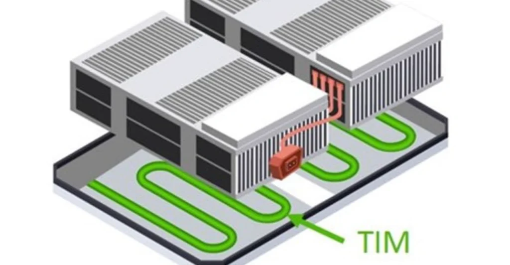
Another key distinction between vehicle and charger TIM requirements is duty cycle. EV power electronics operate under intermittent loading tied to driving behavior, where rapid transients and localized hot spots dominate. In battery packs, as shown in Figure 2, TIM layers transfer heat from battery modules to liquid-cooled cold plates to maintain cell temperature within operating limits.
In contrast, high-power EV chargers operate in near-continuous duty, delivering repeated 150 kW to 350 kW sessions. As a result, TIMs in charging systems must maintain low thermal impedance over thousands of hours at elevated temperatures rather than tolerate short-duration spikes.
These operating patterns drive different thermal cycling profiles. Vehicle electronics cycle from −40°C to +125°C under AEC-Q100 qualification, with frequent micro-cycles induced by power transients. Charging stations typically operate within a 20°C to 45°C enclosure range, although junction hot spots can exceed 200°C during fast-charge sessions.
In EVs, repeated cycling combined with vibration and coolant exposure increases interfacial resistance over time. In chargers, long-duration thermal soak and UV aging of external sealing materials represent the dominant reliability stresses.
Qualification standards codify these stress environments. Automotive-grade TIMs must comply with AEC-Q100 and AEC-Q200 requirements, which specify 1,000 thermal cycles from −40°C to +125°C along with humidity, vibration, and electromagnetic compatibility testing.
Charging infrastructure components generally follow IEC 60068-2 environmental protocols, typically 500 to 1,000 cycles, without the multi-stressor validation matrix imposed in automotive applications.
Weight, vibration, and enclosure design
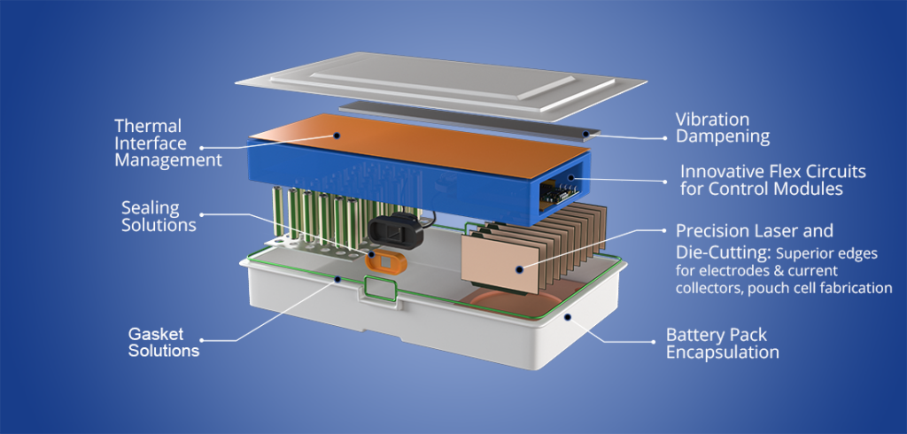
Weight and packaging limit vehicle TIM selection in ways that charger systems do not. As shown in Figure 3, EV battery packs incorporate multiple thermal management, sealing, and vibration-control layers within a tightly constrained enclosure. EV battery packs may use up to five liters of TIM, and heavily filled formulations can add as much as 15 kg to vehicle mass, directly affecting driving range.
This constraint favors thin-bond-line dispensable fillers over thicker gap pads. Charging stations impose no comparable mass constraint, and charger heat sinks can reach 950 mm × 350 mm × 75 mm, dimensions incompatible with vehicle packaging.
Mechanical loading further separates the two environments. Vehicle-mounted TIMs must withstand continuous road-induced vibration from 10 Hz to 2,000 Hz under ISO 16750-3, with acceleration levels up to 20 g for powertrain-mounted components. Soft, elastomeric gap fillers accommodate dynamic deflection while maintaining interfacial contact.
Charging stations remain stationary and are rated primarily for incidental impact under IK08 to IK10 classifications. Without continuous vibration, designers can prioritize thermal efficiency, including rigid phase change materials that would crack or delaminate in mobile applications.
Enclosure strategy reflects these structural differences. Vehicle battery packs seal to IP67 or IP68, and internal TIMs operate within controlled cavities isolated from UV radiation, precipitation, and salt exposure.
Consequently, vehicle reliability concerns focus on coolant compatibility, outgassing, and contact stability under vibration. Charging station enclosures must instead balance ingress protection with airflow and service access.
Even liquid-cooled systems incorporate vents, cable pass-throughs, display openings, and maintenance panels, each requiring gasketing and sealing that maintains environmental protection, EMI control, and thermal stability.
Table 1 summarizes the key differences between EV and charging infrastructure requirements.
| Requirement | Electric Vehicle | EV Charging Infrastructure |
| Duty cycle | Intermittent drive cycles | Near-continuous, back-to-back sessions |
| Primary heat sources | Battery cells, inverter, motor | IGBT modules, rectifiers, DC/DC converters |
| TIM thermal conductivity | 1–3.5 W/m·K | 6.2–8.3 W/m·K (gap pads, gels) |
| Weight sensitivity | Mass directly affects driving range | No significant mass constraint |
| Vibration | Continuous, 10–2,000 Hz, up to 20 g | Stationary; IK08–IK10 impact rating |
| Environmental sealing | IP67/IP68 sealed battery enclosure | IP65/IP66 enclosure with ventilation trade-offs |
| Outdoor exposure | Internal, shielded from UV and precipitation | Direct UV, precipitation, and salt exposure |
| Operating temperature range | −40°C to +125°C (AEC-Q100) | 20–45°C ambient; junction hot spots >200°C |
| Service life target | ~15-year vehicle service life | 10+ years outdoor service |
| Qualification standard | AEC-Q100 / AEC-Q200 (1,000 cycles) | IEC 60068-2 (500–1,000 cycles) |
| Preferred TIM format | Dispensable gap fillers, adhesive TIMs | Phase change materials, high-conductivity gap pads |
Table 1. Comparative TIM requirements: EV vehicles vs. charging infrastructure
Summary
EVs and charging infrastructure operate under different mechanical, thermal, and environmental stresses. These conditions drive distinct TIM, adhesive, and sealant requirements. Vehicles prioritize vibration tolerance, weight control, and automotive qualification compliance. Charging stations prioritize long-duration thermal management and long-term outdoor durability. Both require high thermal conductivity and dielectric strength. Reliability depends on different duty cycles, loading profiles, and enclosure architectures.
References
Thermal Solutions for DC Chargers, Henkel
Solving EV Charging Station Design Challenges: Thermal Interface Materials and EMI Shielding Solutions, Parker Chomerics
Thermal Management for Next-Generation EV Charging, Same Sky Devices
Automotive and EV Charging Sectors: A Deep Dive into Innovative Thermal Management Solutions, YTechUSA
Adhesives and Sealants for Electric Charging Stations, MasterBond
What Methods Are Used for Thermal Management of EV Batteries, PolymerScience
Related EEWorld content
What Role Do TIMs Play in EV Battery Systems?
How Do TIMs Help in Power Electronics Cooling?
Why High-Power DC EV Chargers Require Liquid Cooling Systems
Understanding Reconfigurable EV Battery Packs
What Are the Gas Sensors for Thermal Runaway Detection in EV Battery Packs?