
EVs are transitioning toward high-voltage (HV) standards, which have made energy management requirements more complex. The dc-dc converter serves as a power electronic interface that connects various voltage domains and regulates the bidirectional flow of energy between batteries, traction motors, and auxiliary systems.
The following technical FAQ explains why dc-dc converters are important in EV power electronics configurations and shows their performance benchmarks.
How do dc-dc converters manage multiple voltage domains and energy recovery?
EV power systems balance high-power propulsion needs with the requirements of low-voltage (LV) electronics. Standard architectures rely on a high-voltage traction battery to establish an HV dc bus, typically ranging from 400 V to 800 V. This bus provides the input for the traction inverter that drives the motor, while an onboard rectifier is utilized separately to convert grid ac to recharge the battery.
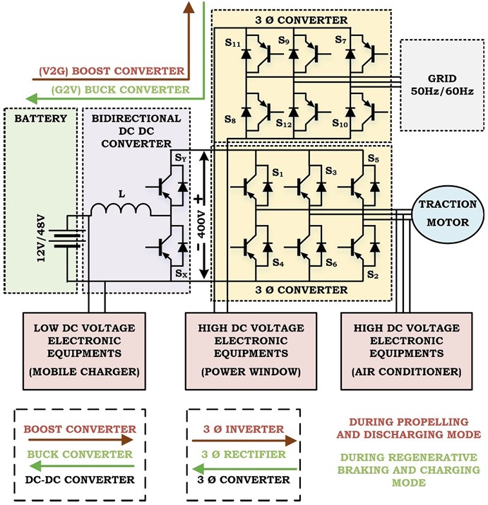
The bidirectional dc-dc converter is placed between the HV bus and the 12 V or 48 V LV supply. As illustrated in the system-level view in Figure 1, this component performs two primary functions:
- System isolation: It safeguards multivoltage domain integration by stepping down HV power for low-voltage auxiliary subsystems. In dual-battery designs, a dedicated 48 V-12 V bidirectional converter further separates sensitive loads (ECUs, sensors, and infotainment) from high-transient auxiliary loads.
- Operational mode management: High-speed digital control allows the converter to switch between propelling, charging, and regenerative braking modes.
Regenerative braking is a critical technical function of the bidirectional dc-dc converter. During deceleration, the traction motor reverses its role to act as an ac generator. The resulting ac power is rectified back to dc. The converter must then regulate this current back into the battery pack.
This process requires precise duty-cycle management to prevent overvoltage at the battery terminals while maximizing kinetic energy recovery. By converting this energy back into stored chemical energy, the system improves overall vehicle efficiency and extends driving range.
Performance trade-offs between advanced converter topologies
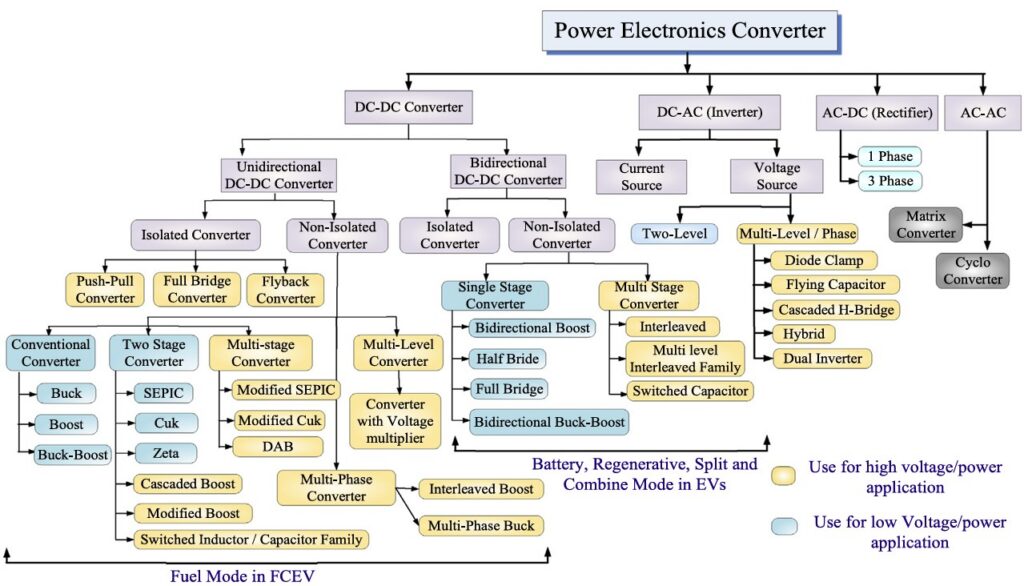
Selecting a dc-dc topology involves evaluating voltage gain, efficiency, and thermal characteristics. Engineers have to deal with a wide range of solutions, as shown in Figure 2. The optimal choice depends on whether the application prioritizes onboard compactness or off-board power capacity.
The specific performance characteristics of these families are detailed in the comparative analysis in Table 1:
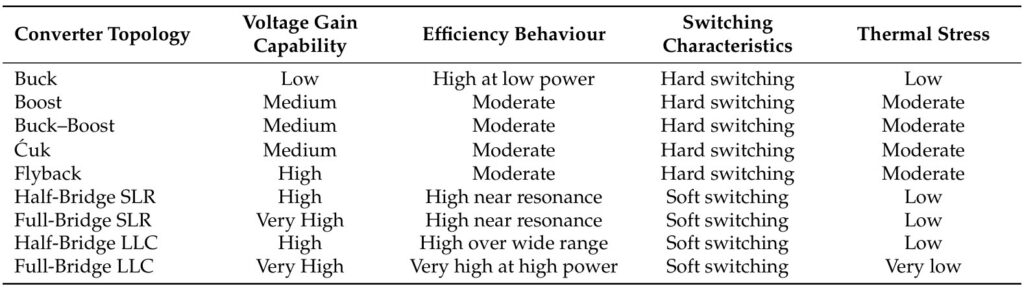
- Non-isolated PWM-based converters: Topologies such as Buck, Boost, and Ćuk converters are used for low- to medium-power applications. These designs offer straightforward control and high efficiency during steady-state operation. However, they use hard-switching, which increases thermal stress and limits scalability for high-power fast-charging applications.
- Interleaved boost topologies: To mitigate the limitations of standard boost converters, engineers often deploy interleaved multiphase designs. By shifting the switching instants of each phase, these converters use harmonic cancellation to reduce input and output current ripple. This technical approach allows for smaller passive magnetic components and improves thermal distribution across multiple semiconductor devices, making it ideal for high-efficiency dc links.
- Isolated resonant converters: In applications where galvanic isolation is required for safety or system protection, resonant topologies such as Half-Bridge or Full-Bridge LLC are utilized. These employ soft-switching techniques (ZVS/ZCS) to ensure that the voltage or current is at zero during transitions. This significantly reduces EMI and switching losses, enabling higher voltage gain and efficiency.
How do wide bandgap (WBG) materials and industry standards impact efficiency?
Silicon (Si) semiconductors have physical limitations regarding thermal management at high frequencies. When switching frequencies increase beyond the conventional 10–30 kHz range to reduce the size of magnetic components, Si-based converters experience higher power losses.
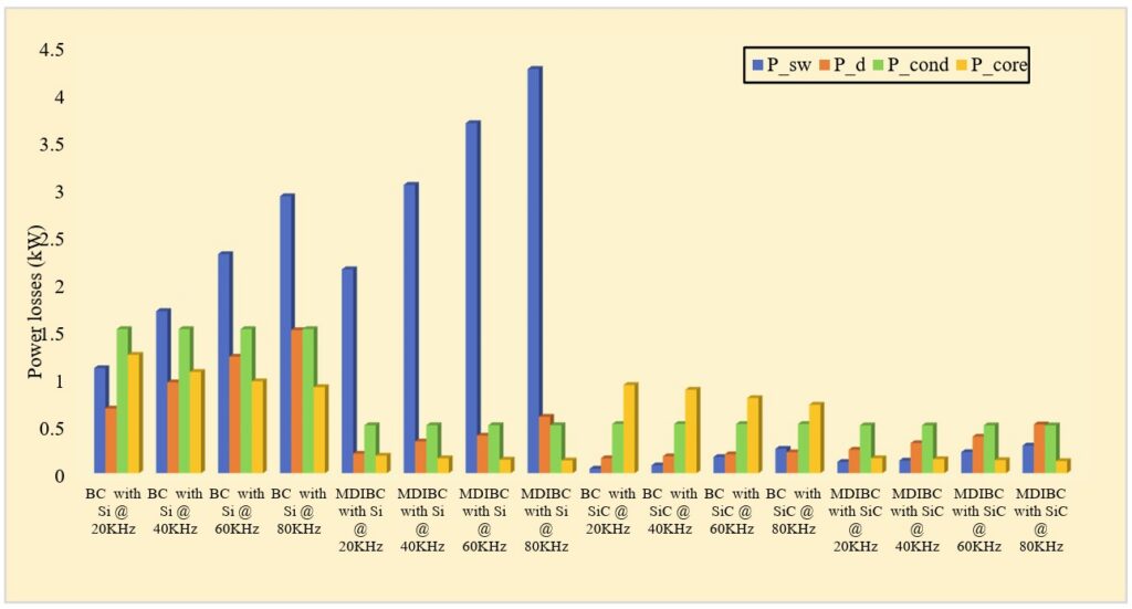
As shown in Figure 3, in configurations such as the standard Boost Converter (BC) or the Multidevice Interleaved Bidirectional Converter (MDIBC), Si-based designs are limited by significant switching and conduction losses. As frequency rises, these losses increase exponentially, creating substantial thermal management challenges.
Silicon Carbide (SiC) and Gallium Nitride (GaN) semiconductors mitigate these issues. WBG materials exhibit better electrical properties, including lower turn-on and turn-off characteristics and lower recovery loss. While high-frequency operation increases ac core and conduction losses as a total percentage of the share, the reduction in switching losses enables improvements in power density and efficiency.
Summary
The dc-dc converter is what makes the modern EV’s value proposition possible. It turns high-voltage potential into safe, usable energy for all of the systems on board. The industry is moving toward 800 V architectures and ultra-fast charging. The combination of advanced resonant topologies and wide-bandgap materials like SiC will be the key to overcoming the thermal and efficiency limitations of older silicon.
References
DC-DC Converter Topologies for Electric Vehicles, Plug-in Hybrid Electric Vehicles and Fast Charging Stations: State of the Art and Future Trends, MDPI
Comparative Performance Analysis of Isolated and Non-Isolated DC–DC Converters to Advance Electric Vehicle Charging Infrastructures, MDPI
Advanced DC–DC Converter Topologies for Electric Vehicles: Wide Bandgap Technologies, Emerging Trends and Future Challenges, Wiley
The state-of-the-art of power electronics converters configurations in electric vehicle technologies, Elsevier
EEWorld Online related content
Bidirectional power for EVs: the practical and creative opportunities using power modules
How do onboard chargers differ between 400 and 800-V EV architectures?
How silicon-carbide technology can address high-voltage EV challenges
What role do wide bandgap semiconductors play in EVs?
Handling the 48-to-12-V stepdown
Powering EVs with silicon carbide