
A full-bridge four-active-element strain-gauge configuration doubles bending-strain measurement sensitivity compared with a half-bridge implementation.
In this series on strain gauges, we’ve looked at quarter- and half-bridge configurations. In this final part, we will look at a full-bridge implementation with four active elements.
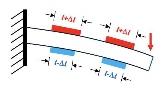
Q: Where do these active elements get placed on our test specimen?
A: Figure 1 shows one possibility. With stress applied in the direction of the arrow, the red elements on top, each of length l in the unstressed state, will expand by Dl, and the blue ones of the same initial unstrained length will contract by Dl.
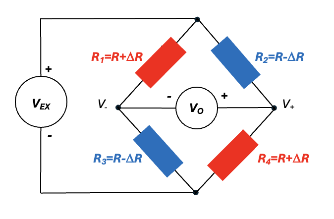
Q: How do we connect these elements?
A: Figure 2 shows these elements connected in the Wheatstone-bridge circuit, where VEX is the excitation voltage, and VO is the output voltage proportional to strain e.
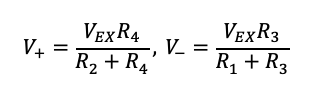
Q: How do we derive strain from VO?
A: We basically have two voltage dividers with the voltages at the positive and negative terminals of our voltmeter as follows:
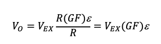
Then, VO is V+–V–:

Given a gauge factor (GF), we want to find VO as a function of strain. From part 3, we know we can substitute R(GF)e for DR:
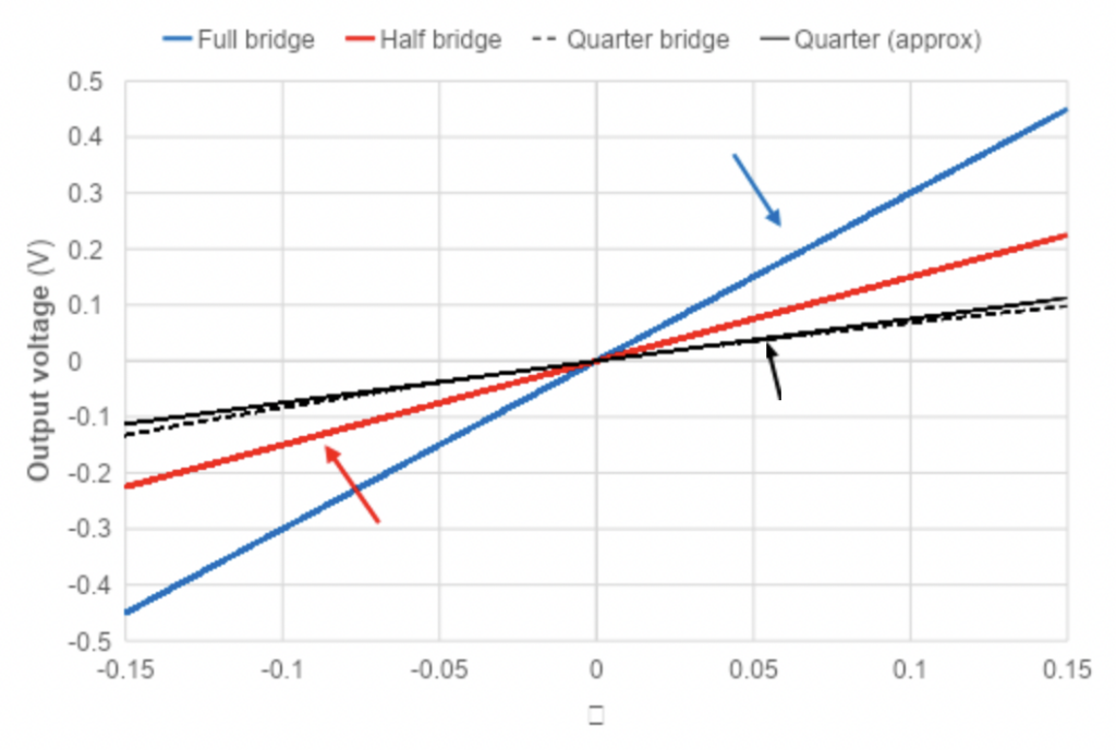
For GF = 2, the Figure 3 traces show VO as a function of e for full-, half-, and quarter-bridge circuits along with the corresponding equations. Note that for the quarter-bridge case, the equation represents a linear approximation (black trace) of the actual nonlinear response (dashed black trace) that we calculated in part 2. Note that as we double the number of active elements, VO doubles, thereby increasing our measurement sensitivity.
Q: Couldn’t we also increase sensitivity by increasing the excitation voltage?
A: Yes, increasing the excitation voltage would increase the sensitivity and signal-to-noise ratio. However, this approach has a downside: it increases power dissipation in each strain-gauge element, with power increasing with the square of the excitation voltage. As power increases, the gauge becomes susceptible to self-heating, which can cause the gauge to expand and contract relative to the test specimen [1], thereby introducing a thermal error that is difficult to compensate for. Consequently, the excitation voltage should remain as low as possible while maintaining an adequate signal-to-noise ratio.
Q: What about lead-length resistance while measuring strain on large structures such as wide-body airframes?
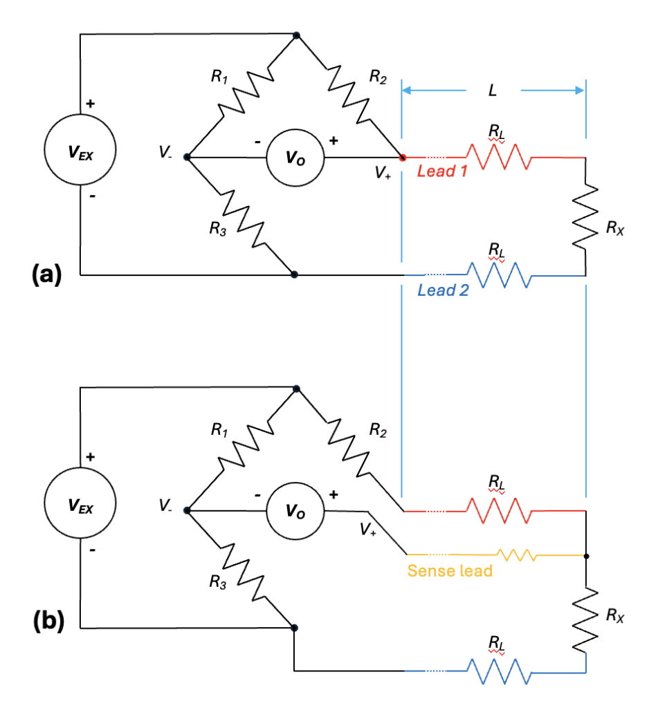
A: As illustrated in Figure 4 in a quarter-bridge configuration, our strain gauge RX attaches to our data-acquisition system through two leads, Lead 1 (red) and Lead 2 (blue), of resistance RL each, so our meter will respond as if RX=RX+2RL. If we know RL, we can compensate, but RL will vary with ambient temperature, making it difficult to know its value exactly.
The gold-standard approach for compensating for lead resistance is to use a four-wire Kelvin measurement, but that incurs additional cost. With the Wheatstone bridge, however, we only need to add one additional sense lead and make a minor wiring change, shown in orange in Figure 4b. Note that with this approach, we’ve moved the Lead 1 resistance from the bottom right of the bridge to the top right, while the Lead 2 resistance remains in the bottom right. Consequently, the bridge will cancel out any resistance changes due to temperature, as described in an earlier article. Of course, the sense lead has some resistance, but it’s negligible compared to the voltmeter’s impedance.
Reference
[1] Strain Gauges: Selecting an Excitation Voltage, SiemensRelated EEWorld Online content
Defining and measuring strain: part 1
The basics of Kelvin connections
Making sense of test circuits with Kirchhoff’s laws: part 4
What’s the difference between 2-, 3-, & 4-wire RDT sensing?
Stress & Strain, Part 1: fundamental principles
How to avoid errors in low-voltage measurements