
High-current electric vehicle (EV) connectors in traction, battery pack, and DC fast-charging applications operate under continuous electrical stress, mechanical loading, and thermal cycling. For high-voltage power paths, designers target contact resistance in the low-milliohm range, typically around 1–2 mΩ per contact at a few hundred amperes, as even small increases drive significant local temperature rise in compact housings.
Stable contact resistance over service life depends on understanding how resistance develops and how degradation is detected. Design, materials, and thermal management then determine how effectively resistance stays within acceptable limits.
This article reviews the mechanisms that increase contact resistance in high-current EV connectors, the laboratory and in-field methods used to monitor it, and the design and thermal strategies that limit resistance growth.
How contact resistance develops
In high-current EV connectors, the nominal contact area is much larger than the real asperity contact spots, or a-spots, that conduct current. As shown in Figure 1, electrical conduction occurs at discrete asperity contact spots, where current constriction and surface films contribute to contact resistance. Any reduction in the a-spot area increases resistance.
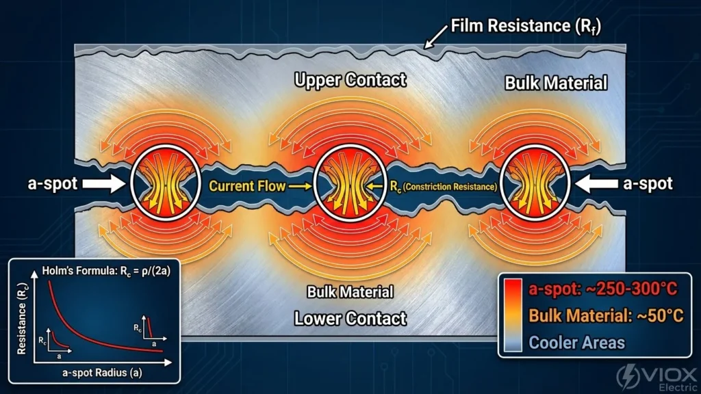
Several mechanisms drive this reduction over time. Fretting and vibration induce micro-motion at the contact interface under thermal cycling and mechanical loading. This motion disrupts protective films and allows oxides and debris to accumulate, reducing the number of conductive a-spots and increasing local resistance. Corrosion and oxidation further degrade the interface in outdoor and under-hood environments, where humidity, salt, and pollutants attack copper or base alloys where plating is thin, porous, or damaged.
Loss of contact force is another contributor. Spring and beam contacts relax at elevated temperatures, and bolted joints lose torque over time, reducing normal force and shrinking the real contact area. Repeated mating cycles accelerate wear, strip plating, expose base metal, and deform contact surfaces, increasing resistance over the connector’s life.
These mechanisms interact through a thermal feedback loop. Higher resistance generates I²R heating, which accelerates annealing, relaxation, and oxidation, further increasing resistance and temperature. This feedback loop requires early detection and mitigation.
Monitoring contact resistance
Engineers measure contact resistance through laboratory qualification before product release and in-field monitoring during service.
As shown in Figure 2, four-wire (Kelvin) low-ohm measurement establishes the baseline, separating current injection and voltage sensing paths to eliminate lead resistance errors in low-resistance measurements.
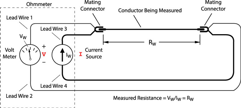
A controlled current is injected, and the resulting millivolt-level drop is measured.
Standards-based sequences defined in IEC 62196, IEC 61851, UL 2251, and automotive connector specifications require maximum contact resistance measurements and stability verification after thermal cycling, vibration, salt spray, humidity, and mechanical endurance testing. Cycle and fretting rigs automate repeated mating and controlled vibration while logging resistance to capture wear-out trends and step changes.
Temperature-rise testing complements direct resistance measurement. Current is ramped to rated or overload levels while monitoring contact temperature. Excessive temperature rise at a given current indicates elevated resistance or an inadequate thermal path.
In-field monitoring relies primarily on indirect methods, since direct milliohm measurement in an operating vehicle or charger is not practical. Embedded negative temperature coefficient (NTC) thermistors, resistance temperature detectors (RTDs), or on-board IC sensors in fast-charging handles and high-voltage junction boxes detect abnormal temperature rise at a given current, flagging contact degradation before a hard fault occurs.
Model-based estimation measures DC link voltage and current, subtracts modeled cable and internal resistances, and attributes the remaining loss to contact resistance. Some algorithms track incremental voltage drop during normal operation and flag deviations from a learned baseline at the same current.
For fleet chargers and serviceable high-voltage joints, periodic micro-ohmmeter testing measures contact resistance directly and compares it against baseline values, typically combined with visual inspection for discoloration, melting, or pitting.
Contact geometry and materials
Contact geometry is the primary design variable for maintaining low and stable resistance. Multi-point contact architectures, including spring fingers, circumferential tongue arrays, and split-beam designs, create many parallel contact spots.
As shown in Figure 3, crown spring and similar multi-point contact geometries distribute current across multiple contact locations and maintain contact force and electrical continuity.
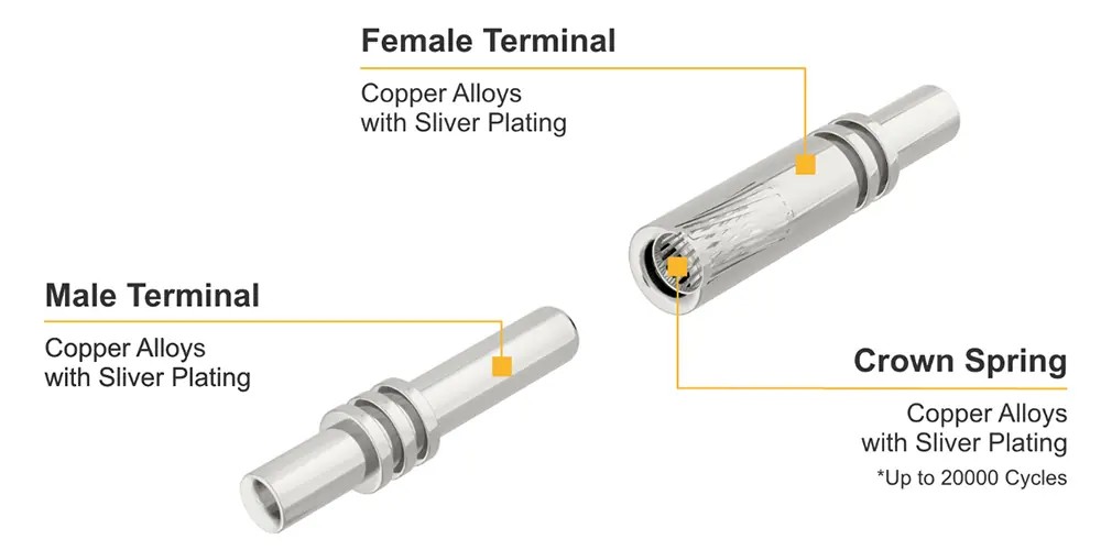
This configuration lowers effective resistance and maintains electrical continuity despite local damage or micro-opening under vibration.
Sufficient normal force is critical. Engineers tune spring geometry and materials to keep force within a stable window across temperature and lifetime without excessive insertion force or accelerated wear. Contact shapes with wiping action during mating disrupt surface films and expose fresh metal at the a-spots.
Beyond contact geometry, material and surface engineering address corrosion, fretting, and film growth that increase resistance. Copper and selected copper alloys provide low bulk resistivity and adequate spring properties while balancing mechanical strength and resistance to stress relaxation.
For high-current interfaces, silver plating is widely used in DC fast-charging and high-voltage battery connectors. It provides low contact resistance, high thermal conductivity, and stable oxide behavior compared with copper or tin. Reported temperature reductions depend on geometry and loading. Plating thickness and porosity are tightly controlled to maintain consistent performance over connector life.
Tin over nickel underplates support cost-sensitive applications at lower currents and temperatures, where nickel barrier layers limit base-metal diffusion and corrosion. Sealed housings with gaskets and IP-rated interfaces reduce exposure to moisture and salt that would otherwise degrade plating and increase contact resistance.
Thermal management and derating
Thermal management is crucial for resistance control, as contact resistance and temperature form a coupled system. Designers use larger conductor cross-sections and multiple parallel contacts to reduce current density at the contact interface and crimp terminations.
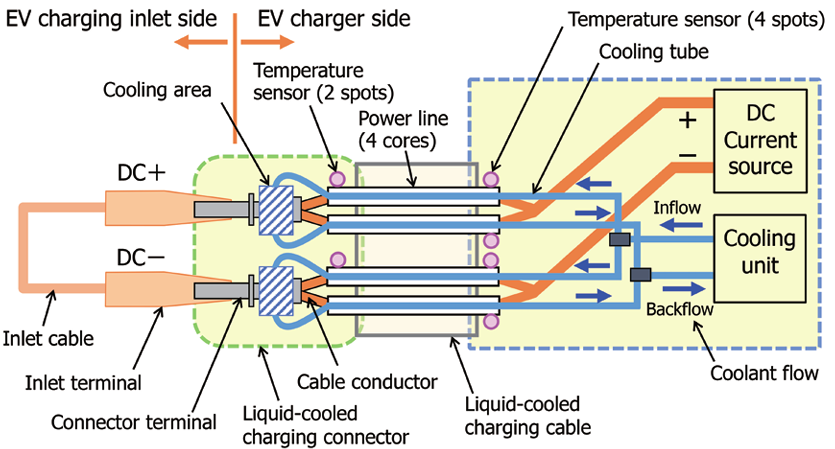
For mid-power connectors, air-cooled housings with optimized thermal paths provide adequate heat dissipation. Ultra-fast DC charging connectors operating above 600 A often use liquid cooling near the contacts. Liquid-cooled cables can be lighter than equivalent air-cooled designs at the same current capacity while maintaining acceptable contact temperatures.
As shown in Figure 4, liquid-cooled charging connectors route coolant near the contact interface and integrate temperature sensing to manage heat generated by high current density.
System-level current limits derate with ambient and measured contact temperature to avoid operating conditions where contact relaxation and oxidation accelerate. Connector standards require temperature rise at rated current to remain below specified thresholds, confirming that resistance and thermal paths remain within limits.
In 800 V architectures, contact resistance management introduces additional constraints. Partial discharge becomes a practical design concern at higher voltages and can couple with resistance drift as a distinct failure mode. Localized resistance increases generate heat, reduce insulation resistance, and can initiate partial discharge along paths that would otherwise remain within specification.
This interaction requires engineers to address contact resistance control and insulation coordination as linked design requirements.
Summary
Increased contact resistance in high-current EV connectors results from fretting, corrosion, contact force loss, wear, and the thermal feedback these mechanisms create. Laboratory qualification using four-wire measurement, environmental testing, and temperature-rise analysis establishes baseline performance and validates connector life.
In-field monitoring relies on temperature sensing, model-based estimation, and voltage diagnostics to detect resistance drift before failure. Multi-point contact geometries, controlled normal force, appropriate plating, and sealed housings address the primary material and mechanical drivers of resistance increase. Thermal management using reduced current density, liquid cooling at high power levels, and active derating keeps the contact interface within a stable operating range.
References
Automotive High-Voltage and Isolation Leakage Measurements Reference Design, Texas Instruments
Detection of Electric Contact Resistance Variations in Automotive Connectors, IEEEXplore
Electrical Contact Reliability of EV Connectors and the Application of Copper Materials, Guchen Electronics
What is Contact Resistance Test and Why is Contact Resistance Testing Done, PowerQualityBlog
Experimental Analysis of Factors Affecting Electrical Contact Resistance in the Bolted Electrical Connections of Power Batteries, ScienceDirect
About Contact Resistance You Should Know, Kuke Electronics
Contact Resistance, ElintaCharge
Understanding Contact Resistance in EV Connectors: Why It Matters for Fast Charging Reliability, WorkersBee
Related EEWorld content
How 800 V+ Architectures Impact EV Connector and Contactor Requirements
What Engineering Requirements Shape EV High-Voltage Connectors and Contactors?
Where Are Liquid-Cooled Connectors and Connectors for Liquid Cooling Used in EVs?
How Sensing Technologies Improve EV Connector and Contactor Safety
How Adhesives and Sealants Impact EV Connector Reliability and Service Life