
This classic piece of test equipment shows the care that went into its design.
On my most recent visit to a swapfest, I purchased a Fluke 8050A benchtop DMM just to take it apart. This 4½-digit classic meter features an LCD display and pushbutton operation. There’s no auto-ranging, so you have to push the buttons yourself. The 8050A measures voltage, current, resistance, and conductance. It can provide min/max relative readings, and it can display measurements in dBm. Fluke offered the 8050A was also available line powered or battery-powered. Here’s what I found inside the case.
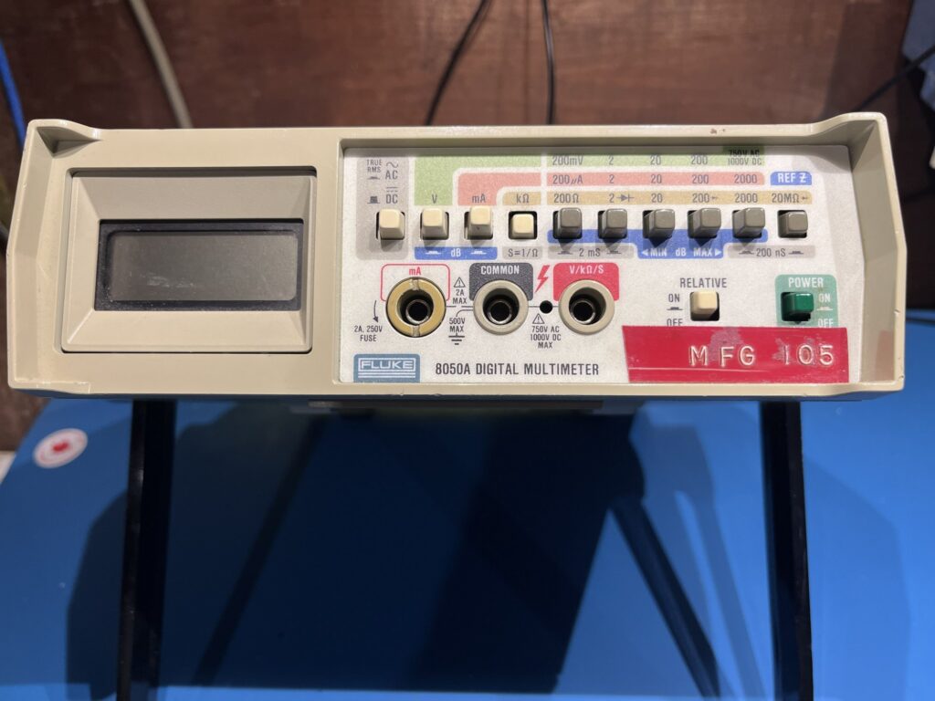
Opening the unit was easy. Figure 1 shows the front panel. The rear panel has a receptacle for a power cord. A single screw holds the entire chassis to the case, making for easy servicing. There is nothing else on the rear panel: no controls, no connectivity.
Sliding the PCBs out of the DMM’s case reveals two boards. The main board holds the power supply, microcontroller, analog circuits, and switching circuits. A daughter card holds the display drivers. The boards are connected through a flat ribbon cable.
The display board is dated 1979, while the semiconductors throughout the meter have 1993 date codes. The manual, which you can download from Fluke, has a 1984 print date.
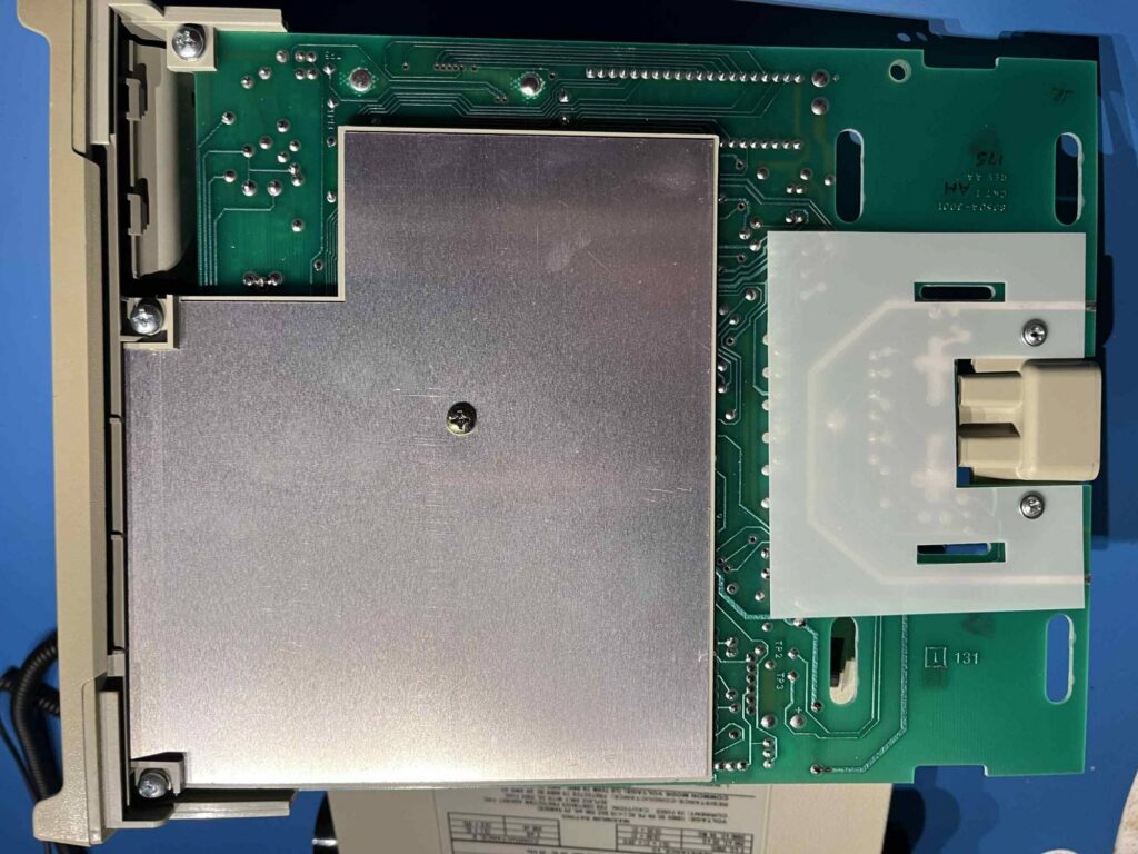
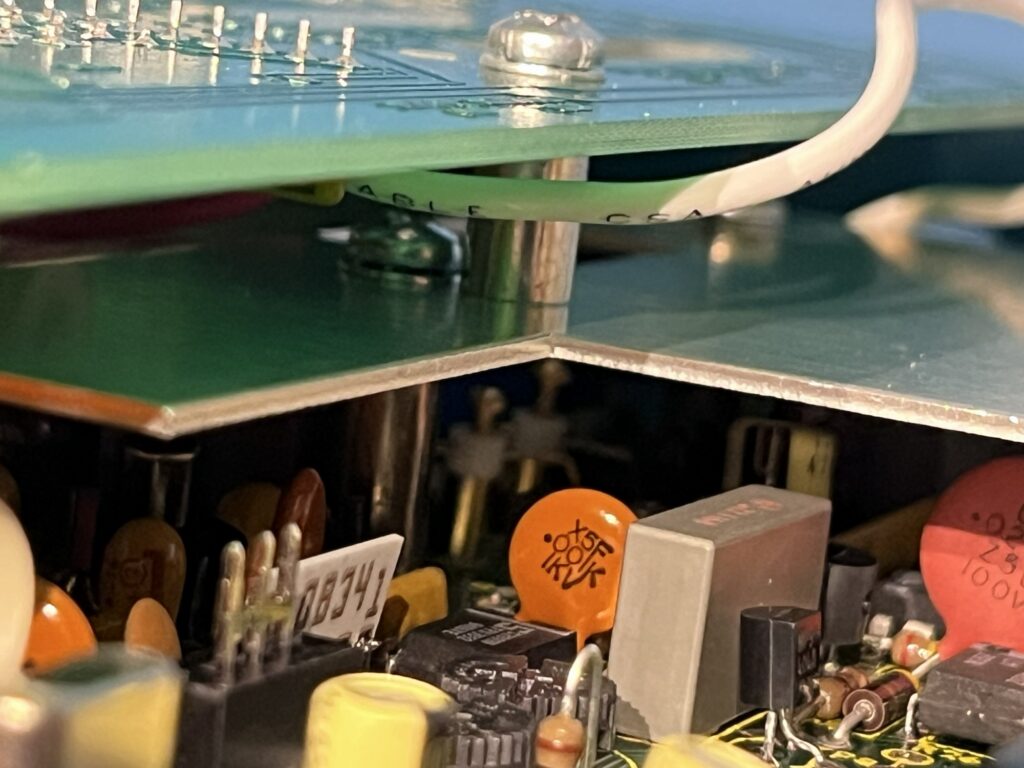
The designers went out of their way to shield the analog circuits by using two aluminum plates. One mounts under the main board, shown in Figure 2. A plastic plate under the aluminum plate prevents shorting. Another aluminum plate mounts on the main board and resides over the sensitive circuits, shielding them from the digital circuits above (Figure 3). As you’d expect, both plates connect to circuit ground.
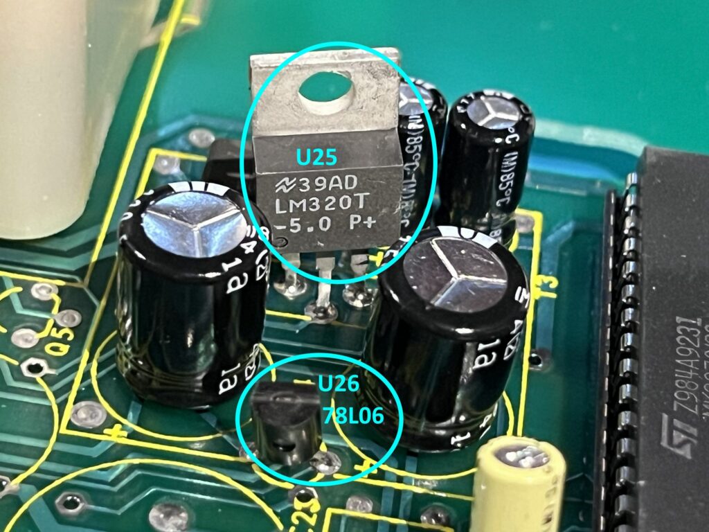
The 8050A power-supply circuit in Figure 4 uses an LM320T linear regulator that produces a -5 V DC rail. Other power rails are an unregulated +13 V rail and a 6 V regulated rail. These circuits follow a diode bridge that follows the AC mains transformer. An 8-bit microcontroller sits right next to the power circuit. You could do that in those days because of the linear voltage regulator. Today, EMI from switching regulators could interfere with the microcontroller’s operation, requiring some distance and shielding.
The LM320T shown in Figure 4 is part of the -5 V supply and is designated as U25 on the schematic, board layout, and bill of materials (BOM). The BOM, however, does not provide a manufacturer’s part number. Instead, it duplicates Fluke’s internal part number. Clearly, it’s an LM320T.
The documentation also lacks identification for U26, the 6 V voltage regulator. Again, the parts list uses Fluke’s internal part number. U26 is a 6 V regulator, 78L06.
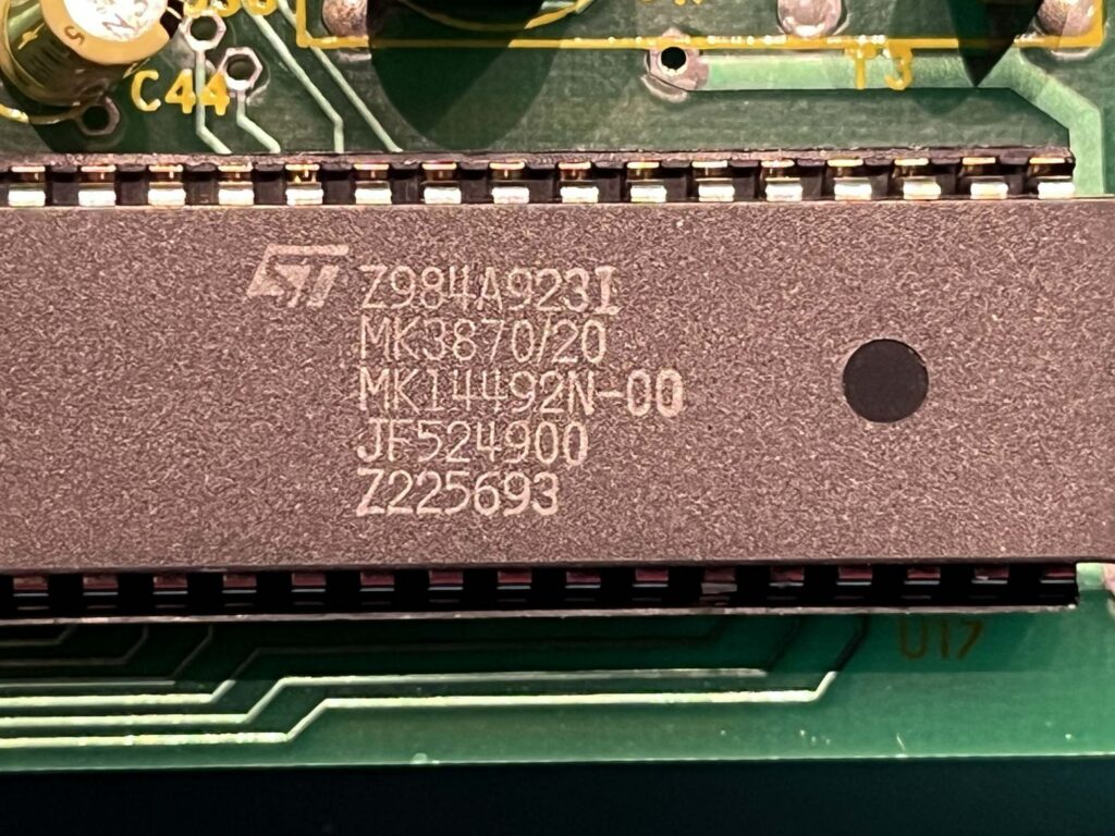
The microcontroller in Figure 5 carries an ST logo, though it’s actually a Mostek MK3870. Mostek was acquired by United Technologies in 1980, selling the operation to Thompson Electronics in 1985, which later became STMicroelectronics. The 1993 date code and the ST logo indicate that the part was manufactured by ST when the meter was assembled. Other codes on the part indicate that it contained a special mask just for this application.
The meter’s main-board schematic, shown in Figure 6, contains the measurement circuits, microcontroller, and power-supply circuits. The power circuits appear on the digital board’s schematic simply because it had plenty of space for them, and the main board schematic is quite crowded.
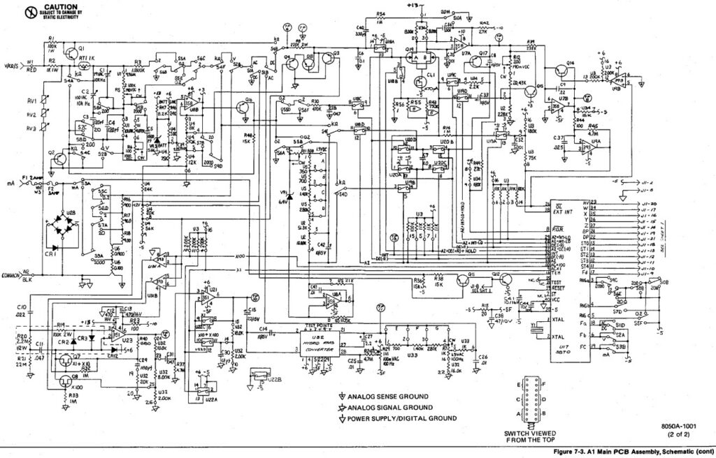
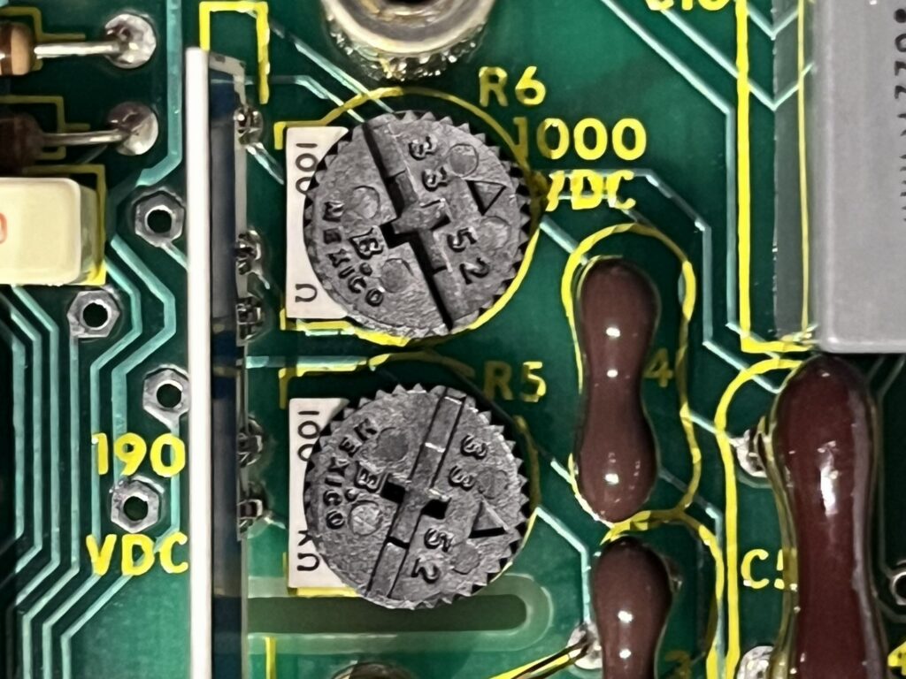
The measurement circuits consist of LM358 op-amps, LM393 comparators, bipolar transistors, MOSFETs, Zener diodes, switches, and passive components. The semiconductors are still active parts, though you may have trouble procuring them in DIP packages. As Figure 7 shows, calibration was performed by adjusting board-mounted potentiometers.
The main board contains a small mystery: a hybrid RMS converter, shown in Figure 8. The 8050A schematic shows this circuit as a box with no details other than it’s clearly part of the AC measurement circuit.
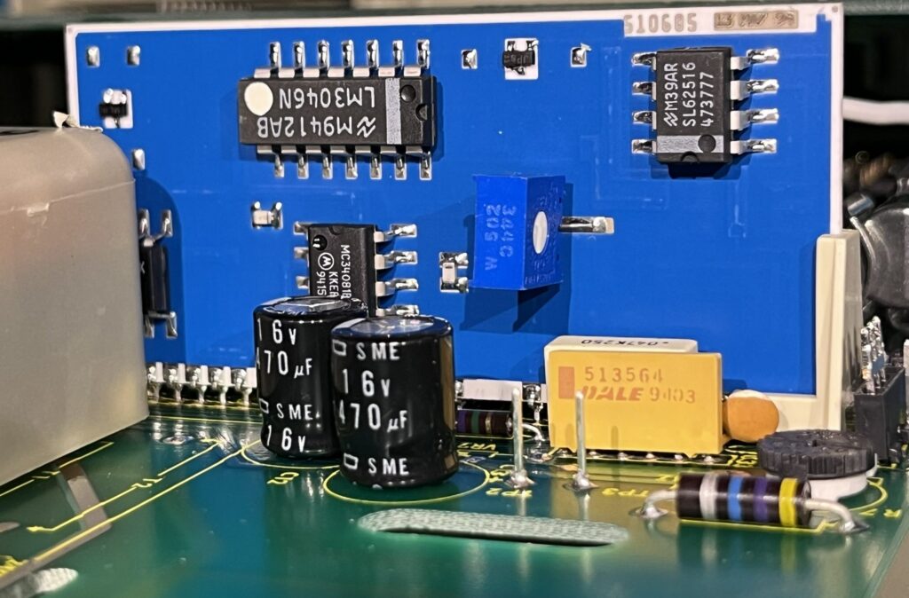
It’s a vertically mounted ceramic substrate that contains several components.
- LM3046: A second-source part for the CA3046, which contains five bipolar transistors. While the part shown in Figure 7 was from National Semiconductor (now Texas Instruments), it was manufactured by several companies, including Harris and Intersil.
- SL62516: Apparently from National Semi, this part has no reference on ti.com. An AI search turned up nothing. If you know what it is, please leave a comment.
- MC34081: A high slew rate, wide bandwidth, JFET input op amp. It has a bandwidth of 8 MHz and a slew rate of 25 V/µs. Those were impressive specs at the time.
- LF351: Hidden behind the AC mains transformer. The LF351 is a JFET-input single op amp that’s still available.
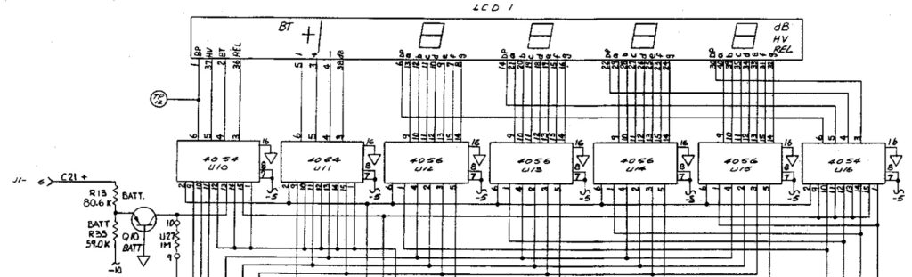
The digital board shown in Figure 9 contains seven LCD driver ICs: Three CD4054 4-segment drivers control indicators where two indicate functions such as ±, dB, HV, REL (relative) functions and the leftmost digit, which is either off or shows a “1” digit. That’s what gives the meter its most significant “half digit.” A third CD4054 controls the decimal points for the four full (0-9) digits. Four CD4056 BCD-to-7-segment display drivers control the four full digits. These parts were manufactured by Harris Semiconductor. Both the CD4054 and CD4056 are still available, even in the original DIP packages.

Figure 10 shows the schematic for the LCD and drivers.
The Fluke 8050A was a basic bench DDM and was a workhorse in its day. Its designers provided good shielding through the use of two grounded aluminum plates. Today, that shielding might use multilayer PCBs instead of the plates and double-sided boards. Multilayer boards would streamline assembly. Also impressive was the fact that none of the aluminum electrolytic capacitors showed any sign of bulging, even after 33 years.
Related EEWorld Online content
Swapfest: A truckload of test equipment
Tryout: two low-cost USB inline meters and a load
Swapfest May 2025: test equipment
Teardown: HP 8112A pulse generator
Flea market vintage test equipment, September 2024
What’s a half digit and are they all the same?
The factors of accurate measurements
Things to know about multimeters