
Electrical leakage current flows through every real circuit, even when everything is operating correctly. It is not a fault current. No insulation has failed, and no short circuit has occurred.
This technical FAQ examines what leakage current is at the circuit level, where it originates in industrial systems, and why strict safety standards exist to control it.
Q: How does current become leakage current?
A: In an ideal circuit, every ampere that leaves the source returns through the neutral conductor. The live and neutral conductors carry equal and opposite currents, so their vector sum is zero.
In practice, some of that outgoing current finds an alternative path to earth. It escapes through imperfect insulation, through parasitic capacitances to chassis, or through Y-capacitors in electromagnetic compatibility (EMC) filters. The portion that does not return through the neutral is the leakage current.
Figure 1 illustrates this principle using a single-phase, three-wire measurement setup.
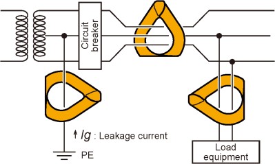
When a clamp meter surrounds both conductors simultaneously, their opposing magnetic fields cancel, leaving only the imbalance to register on the instrument. That imbalance is leakage current Ig, which returns via the protective earth (PE) conductor.
In a zero-leakage circuit, the clamp reads zero. Any non-zero reading means the current is taking an unintended path to earth under normal operating conditions. The International Electrotechnical Vocabulary (IEV 195-05-15) defines this precisely as “electrical current in an unwanted conductive path under normal operating conditions.”
Q: Why do variable-speed drives produce significant leakage current?
A: In a variable-speed drive (VSD) system, leakage current accumulates from four sources operating simultaneously. Figure 2 shows how those sources span the full drive chain, from the EMC input filter to the motor itself.
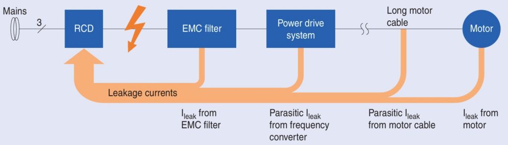
The first source is the EMC filter. Y-capacitors connect the phase conductors to earth, and the leakage they produce scales with mains frequency, voltage, and capacitor value. Engineers add them deliberately to suppress conducted emissions, making the leakage an accepted trade-off for EMC compliance rather than a design flaw.
The second and third sources are the frequency converter and the shielded motor cable. Switching transitions in the converter drive current through parasitic capacitances to earth, and motor cables exceeding 200 m add significant distributed capacitance. The fourth source is the motor winding, which couples capacitively to the motor frame.
The residual current device (RCD) sees the aggregate of all four sources. Even when each contribution is small, their sum can exceed the 30 mA trip threshold for personnel protection, causing nuisance tripping with no actual fault present. Active leakage current filters address this by sensing the total residual current and injecting a 180° phase-shifted cancellation current before it reaches the RCD.
Q: How much leakage current is dangerous?
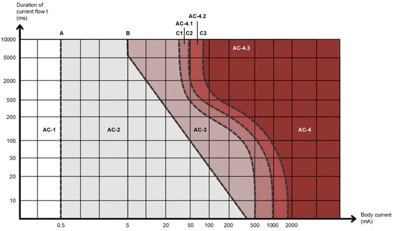
A: Leakage current becomes a safety hazard when it finds a path through a person, and the severity depends mainly on current magnitude, duration, and current path. Figure 3 illustrates the IEC 60479-1 AC shock zones: AC-1 is generally imperceptible, AC-2 is perceptible but not harmful, AC-3 can cause muscle contraction and difficulty letting go, and AC-4 includes increasing probabilities of ventricular fibrillation. The exact zone boundaries vary with duration and current path, so AC-4 cannot be reduced to a single fixed current threshold.
Dry skin presents a resistance of roughly 20 to 30 kΩ/cm². Wet or broken skin drops that resistance by up to 100 times, substantially lowering the voltage needed to drive a dangerous current through a person.
These physiological realities drive the strict limits in IEC 60601-1 Edition 3.2 for medical equipment. Earth leakage current is capped at 500 µA under Normal Condition (NC) and 1,000 µA under Single Fault Condition (SFC). Touch current limits are 100 µA (NC) and 500 µA (SFC). For cardiac floating (CF) applied parts, patient leakage is limited to 10 µA (NC) and 50 µA (SFC).
Summary
Leakage current flows through parasitic capacitances, imperfect insulators, and intentional EMC filter components in every real electrical system. Unlike residual current, which signals an insulation fault, leakage current is always present under normal operating conditions. Its sources are manageable through filter topology, cable length, shielding, and active cancellation. Standards such as IEC 60990, IEC 60601-1, and EN 60939 translate the biological risk defined in IEC 60479-1 into specific engineering limits.
When measuring capacitor leakage, engineers must wait for two post-application transients to settle. The instantaneous charging current and the slower dielectric absorption current both distort an early reading. Only the flat, steady-state insulation resistance current represents true leakage.
References
3-Line Active Filter LeaXield for Leakage Current Compensation, TDK Electronics
Capacitance Leakage Current Measurement Techniques Using the B2985A/87A, Keysight
Leakage Current Considerations for Medical Power Supplies, Industry EMEA
Leakage current measurement, HIOKI
EEWorld Online related content
Parasitic capacitance, inductance, and displacement current
Robust design for Variable Frequency Drives and starters
Safety capacitors for EMI filtering and voltage isolation
Identifying the right medical power supply
Basics of ground fault interrupters
FAQ on X- and Y-capacitors