
Phase Locked Loop, PLL, DPLL, ADPLL, VCO, Phase Detector, Loop Filter, Closed Loop, and Synthesizer.
PLL Dynamics
- The PLL is inherently a dynamic device, tracking inputs and dealing with transients and upsets. A PLL operates through three primary dynamic states:
- Free-running mode: The VCO operates at its free-running “natural” frequency before lock.
- Capture: The PLL actively pushes 𝑓𝑂𝑈𝑇 toward the reference frequency based on the loop bandwidth and 𝐾𝑉𝐶𝑂 as it attempts to lock.
- Phase-locked: The system achieves synchronization with acceptably low phase error (typically less than a fraction of one degree) and fast lock times. In this state, the output signal is fully synchronized in both phase and frequency with the reference. The PLL maintains this lock by continuously making subtle adjustments to the VCO, responding to even tiny variations in the reference signal to ensure robust stability.
Loop stability and bandwidth configuration are baseline aspects of PLL design, directly impacting both the dynamic response and noise performance of the system. The loop bandwidth of a PLL dictates its responsiveness to changes in the input reference or other system disturbances. A wider bandwidth generally leads to these attributes:
- Faster tracking: The PLL can quickly lock onto and follow variations in the input signal.
- Reduced reference spur filtering: It is less effective at filtering out unwanted spurious signals from the reference.
- Lower in-band phase noise: It can better suppress noise within the operating band, as seen in wideband designs.
However, these come with trade-offs. A wider bandwidth also allows more of the VCO’s intrinsic noise to reach the output, and this heightens the risk of loop instability. Conversely, a narrower bandwidth often used in low-jitter designs offers several benefits:
- Enhanced VCO phase noise suppression: It more effectively filters out noise generated by the Voltage-Controlled Oscillator.
- Improved noise shaping: It can better shape the noise spectrum for the desired performance.
The drawbacks of a narrower bandwidth include sacrificing settling speed and tracking capability.
The digital PLL
Not surprisingly, as digital process technology and designs took over the implementation of many functions previously done using analog designs, there was an incentive to migrate the analog PLL to a mostly digital design or even an all-digital design called the digital PLL (DPLL).
In general, the DPLL is more robust with respect to noise and process variations compared to analog PLLs, and is obviously easier to integrate with digital circuits in VLSI design. However, it has slightly lower performance in phase noise compared to analog PLLs, and increased design complexity for high-frequency applications.
In the DPLL, the conventional PFD is replaced by a time-to-digital converter (TDC), which directly quantizes the phase difference between the reference ( 𝑉𝑅𝐸𝐹 ) and feedback ( 𝑉𝐹𝐵 ) signals into a digital word. This eliminates the analog charge pump, making the loop mostly digital while preserving the core function of precise phase and frequency comparison, shown in Figure 1.
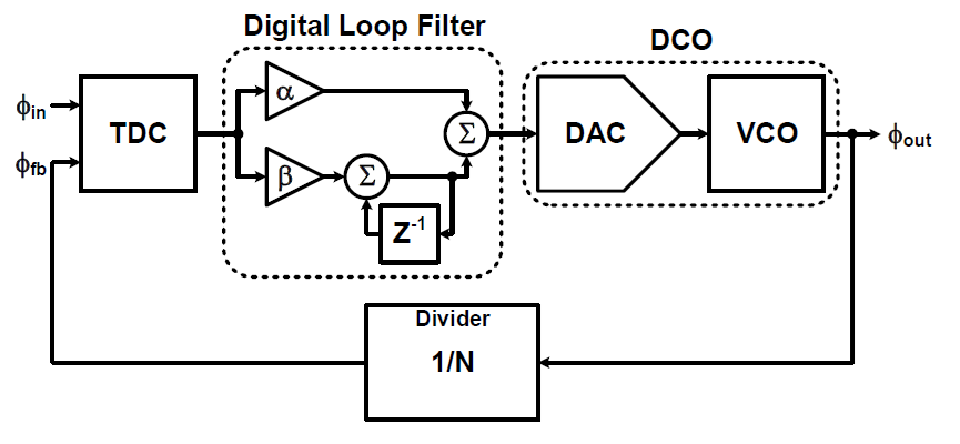
The resulting error signal is then processed by a digital filter. This filter approach allows for precise mathematical manipulation of control parameters, effectively eliminating issues commonly associated with analog component tolerances and environmental variations.
The filtered control signal adjusts a numerically controlled oscillator (NCO), also called a digitally controlled oscillator (DCO), which generates the output frequency. Note that the digital/analog converter (DAC) of the DCO is partially analog, while the VCO is all analog. The term DPLL is thus somewhat of a misnomer, but still used as standard terminology in the industry.
There are several ways to build the TDC. These include the up/down counter, flash, vernier, two-step, interpolating, and the oscillator-based TDC, among others. As usual, the “right” one for a given DPLL application is a function of the priorities, tradeoffs, operating frequency, and IC process capabilities.
The DPLL has advantages compared to analog PLLs:
- Higher immunity to noise: Digital signals are generally more resilient to electrical interference.
- Improved stability: DPLLs exhibit enhanced stability across temperature changes and over time (aging), unlike analog designs.
- Software reconfigurability: Their digital nature allows them to be easily reconfigured or tuned through software. This programmability provides significant real-time flexibility.
That last point is especially important, as one of the standout advantages of DPLLs is that flexibility. Since their loop parameters are controlled by digital filters and algorithms, they can be adjusted to accommodate different frequency ranges and application requirements without hardware modifications.
They can be re-programmed dynamically to meet different signal conditions or environments, and employ advanced algorithms to enhance performance, things which cannot be done with fixed-function analog filters. This inherent flexibility makes DPLLs exceptionally well-suited for applications demanding dynamic frequency synthesis, adaptive clock recovery, and phase synchronization in digital communication networks where SNR and other input-signal perturbations are continuously varying during use.
However, the discrete-time nature of DPLLs introduces some trade-offs:
- Processing delay: While digital control enhances precision and stability, it can introduce a processing delay, potentially limiting the response speed compared to APLLs.
- Quantization noise: The reliance on digital computations can lead to quantization noise, necessitating sophisticated filtering techniques to maintain signal integrity.
- Design complexity and power consumption: The design of DPLLs often involves complex digital algorithms for phase detection and loop filtering, which require computational resources and can increase power consumption.
Going all-digital
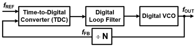
As noted, the so-called DPLL is really a “mostly” DPLL. The next step in PLL evolution is to replace the DAC and VCO with an all-digital equivalent to the VCO, called a digital VCO or a Digitally Controlled Oscillator (DCO), as seen in Figure 4. This is done by using a specialized direct digital synthesis (DDS) arrangement similar to the ones used for frequency tuning in wireless communication systems, or a topology scheme using capacitors that are switched in and out of the circuitry to change its resonant frequency.
What’s next for PLLs?
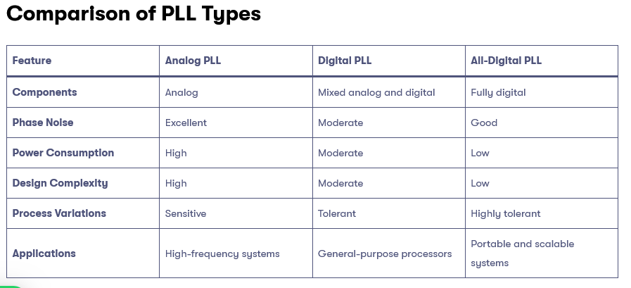
Thus far, we have only looked at the basics of PLLs of all types. Each implementation — analog, digital, or all digital — offers tradeoffs in performance, integration, cost, size, power consumption, and more, summarized in Figure 3.
As a general guide, with today’s process technology, the general “which way to go” guidelines are:
- Analog PLLs for high-frequency, low-jitter applications such as RF communication.
- Digital PLLs for robust designs that integrate easily with digital systems.
- All-digital PLLs for low-power, highly scalable designs that fit well with advanced CMOS technologies.
However, the rapid shifts in user needs, properties, process technology, packaging, and VLSI technology mean that these guidelines have many exceptions. For example, high-performance PLLs are now often embedded in RF ICs that work up to a gigahertz and beyond, which was unimaginable just a few years ago.
To overcome subtle performance issues and improve performance in critical areas needed in a specific application, PLL designers have enhanced the basic designs with many clever “twists”. They have developed numerous add-ons and adjunct circuitry schemes that enhance performance along one or more parameters or suppress undesired attributes, while accepting tradeoffs in other parameters in order to meet system priorities.
For example, Injection-Locked PLLs (ILPLLs) are often used in high-speed communications design. They use a feedforward scheme to inject a corrective signal that is derived ahead of the filter, resulting in superior low-jitter performance and rapid locking times that are often needed in high-speed communications. Similarly, Delay-Locked Loops (DLLs) use a variation of ILPPLs to synchronize phase and delay rather than frequency, and are targeted at clocking applications in digital systems to reduce clock skew.
Conclusion
PLLS in all their variations and topologies are essential building blocks for modern design across a wide range of applications. They are available in pure analog, hybrid analog/digital, and all-digital arrangements, offering benefits and drawbacks with respect to different performance parameters. Clever designs overcome many of these shortcomings with an assessment of cost, size, and power considerations. The versatility, flexibility, and applicability of the PLL make this a viable approach.
There is much more that can be said about PLLs of all three types. Much of this information is available on the web, of course, but there are also textbooks and longer academic and practical works that explore their capabilities, application issues, and subtleties.
References
TUTORIAL: Phase Locked Loops, Integrated Device Technology, Inc.
ECEN620: Network Theory, Broadband Circuit Design, Texas A&M University
A Design Procedure for All-Digital Phase-Locked Loops Based on a Charge-Pump Phase-Locked-Loop Analogy, IEEE Transaction on Circuits and Systems
An Overview of Phase-Locked Loop: From Fundamentals to the Frontier, National Library of Medicine
Types of PLL in VLSI: Analog, Digital, and All-Digital PLLs, Success Bridge
Digitally controlled oscillator, Wikipedia
Three Major PLL Implementations, Movellus
Phase-Locked Loop (PLL) Fundamentals, Analog Devices
Signetics SE/NE 565 PLL Overview, Scribd
The Phase Locked Loop IC as a Communication System Building Block, Texas Instruments
Lecture 080 – All Digital Phase Lock Loops (ADPLL), Georgia Institute of Technology
Related EEWorld Online content
What is Proportional (PID) Control and why is it used? (Part 1)
What is Proportional (PID) Control and why is it used? (Part 2)
RCA & Color TV: A dominant company and standard, both now gone – Part 2
Does 32 kHz or 3.58 MHz mean anything to you? part 2
Synthesized tuning, Part 1: Basic frequency-synthesizer principles
Synthesized tuning, Part 2: Advanced synthesizers and performance