
New and old technologies provide critical tunnel wireless links.
Providing and maintaining wireless, mobile connectivity within underground tunnel-like environments (often described as “tunnel radio”), as well as to the surface, is a challenge for many reasons. Although these are closed and defined spaces and shielded from “outside” signals, they are subject to numerous electrical, mechanical, RF, and other factors that are unlike those of large, above-ground enclosed spaces such as offices, warehouses, hospitals, and similar.
Yet such connectivity is essential. It is needed and mandated for safety, of course, as well as efficient operation; it is also expected by riders on subways. Before the advances in wireless technologies (components, frequencies, size, power, and many more aspects), the only tunnel underground options were of limited range and uncertain reliability via personal walkie-talkie radios or wired phones with their obvious lack of mobility.
This FAQ will look at the tunnel-radio problem and identify some of the available solutions. As expected, there is no single best approach as the chosen approach depends on the specifics of the situation, including distances, flexibility, usage load, new or retrofit, cost, and more. It will then focus on one of these, called “leaky cable” technology.
Note that this underground scenario is often referred to as “tunnel radio” as a shorthand phrase, whether it is an actual tunnel, a mine, or even a subway. However, one of the leading vendors is Tunnel Radio of America Inc, so there is a possibility of confusion (and even perhaps legal action?) when the term “tunnel radio” is used, but we won’t worry about this issue.
Q: What is the nature of the problem?
A: Above-ground and underground wireless infrastructure could not be more different. Above ground, a tower system consists mainly of lines and antennas. Running lines and positioning antennas, while not without challenges, are relatively straightforward when the “ceiling” is the sky. In contrast, the confines of a tunnel present a diverse assortment of challenges—many of which have taken years of engineering and troubleshooting to overcome.
The underground or tunnel environment has many obstacles to a clear signal path, such as signal absorption and more. The path usually has bends and twists, which result in signal blockage. Unlike an enclosed above-ground facility, an underground mine often has changes in pathways, moving obstacles (equipment), and other impediments to a consistent wireless path. Even if the path is static, there are many challenges in providing connectivity across voice, data, Wi-Fi, and even Ethernet.
Q: Why the need for tunnel or underground connectivity?
A: There are multiple reasons. First, there’s basic safety and security for personnel in the tunnel, or the need to read various sensors (many of which are safety-related). Second, regulatory mandates dictate such connectivity for obvious safety reasons. Third, it may be needed for ongoing operational monitoring of processes in the tunnel, such as mining. Finally, it may be needed to meet user expectations for connectivity via Wi-Fi/Internet access.
Q: How was connectivity within and to “above” achieved in the pre-RF past?
A: It wasn’t, or it was done with great difficulty. Wired stations were used, which means personnel had to get to a ruggedized phone” to report in, report a problem, or get information. At the same time, many industrial and mining tunnels were not “static” but were always being extended or new branch-offs were added, meaning new wires had to be installed and maintained. Of course, in the era prior to any electrical connections, underground and tunnel connectivity was accomplished by signal lights, whistles, or couriers, all of which have obvious limits.
Q: What modern electronic approaches are available?
A: Among the most common: 1) the so-called “natural propagation” using small antennas within a tunnel, with the tunnel as a “waveguide, often aided by a network of local repeaters, or a mesh network strung along the path via using cable or optical links as needed), or 2) what are called “leaky” coaxial cables where some of the RF energy in the cable is allowed by design to leak out along the cable length (also with repeaters as needed). Some longer systems use a combination of the two.
Q: What are some of the other considerations?
A: In safety-critical situations, there is also an analysis of failure modes – what happens when a part of the system fails, regardless due to “normal” failure, the harsh operating conditions, or a moving vehicle signal interference? What parts of the system can remain functional, as seen in Figure 1?

Q: Are any of these standardized “drop-in” solutions?
A: Not at all. Each must be carefully designed for the frequencies needed, modulation and data rates, locations, available space, ruggedness, maintenance, DC power needs, battery backup, and many other factors. While it is easy to think that all that is needed is a GHz-band Wi-Fi connection and all will be good, the real world has many more requirements.
For example, there are two-way radios (walkie-talkies) needed for direct person-to-person voice communication, and these operate in special assigned bands that are in the 300-500 MHz part of the spectrum.
While each tunnel challenge is unique, there are some commonalities and representative examples. The situation has been modeled and studied analytically, supplemented by field measurements by researchers (and their graduate students).
Modeling and specifics
Q: Can you give an example?
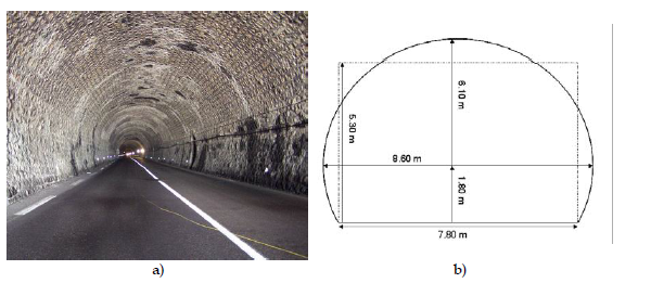
A: Consider a representative 3-km straight tunnel of Figure 2, evaluated with a half-wave 510-MHz transmit (Tx) dipole centered in the tunnel and a corresponding receive (Rx) antenna; the transmitting power is 34 dBm.
Q: What were the results of signal drop-off in this case?
A: Figure 3 shows the decline in the received power at 510 MHz versus the axial distance d between Tx and Rx, the Tx and Rx antennas being both horizontally (HH) or vertically (VV) polarized.

Note that these results are for one frequency; the signal attention and associated dropoff are more severe at gigahertz frequencies.
Q: Is this tunnel a representative scenario?
A: Yes and no. Fairly straight tunnels are used for cars and roadways, but even those tunnels may have bends and turns. However, mining tunnels are often not as straight or smooth-walled as these roadway tunnels, so the signal propagation is much more difficult to analyze or can only be coarsely approximated.
Q: Is the antenna and propagation arrangement viable?
A: Absolutely, if it is in the right circumstances. It has to be carefully specified and engineered to meet the many goals associated with reliability, availability, frequency band or bands to handle, bandwidth, data rate, and more. Keep in mind that some installations need to handle only one band, while others need to support multiple bands and applications, such as gigahertz Wi-Fi as well as 300-500 MHz handheld, dedicated voice walkie-talkies.
Some of the assessments can be done analytically in advance, but much of the effort also relies on experience and past practice, especially as the setting gets more complicated and the connectivity demands increase.
Q: What about an alternative?
A: The leaky-cable approach is the primary alternative and will be discussed in the next part.
References
Radiating Cables, Times Microwave Systems
Radiating Cable: The Answer to the Confined-Space Communications Challenge, Tunnel Radio
On the Right PATH, , Times Microwave Systems
All-in-One Digital Leaky Feeder System, Tunnel Radio
ULTRACOMM Distributed Antenna System, Tunnel Radio
ULTRACOMM System Manual, Tunnel Radio
Challenges of Underground Transportation Wireless Coverage, American Tower
Underground Tunnel Communication Innovations Whitepaper, Innovative Wireless Technologies (IWT)
Wireless Communication in Tunnels, ResearchGate
Leaky Cables, Imperial College/UK
Leaky cables are a good thing, Urgent Communications/Informa
Related EEWorld Online content
Getting one wire to do more, Part 3 – Powering the antenna LNA
Microwave/Millimeter Wave interconnects, Part 1: Coaxial cables
Microwave/Millimeter Wave interconnects, Part 2: Connectors and cable assemblies
Coaxial cable myths and misunderstandings