
We have looked at the “tunnel radio” problem and one solution using one (or likely several) fixed-location distributed antennas. This part looks at an attentive, informally called the “leaky cable” or “leaky feeder” solution.
Q: What is the formal name for this approach?
A: Technically, it is known as a radiating coaxial-cable system. It is a hybrid communication system that employs both wired and wireless features. When properly designed and installed — and installation is not trivial — these systems provide reliable, full-coverage, and portable two-way radio communication for confined-space environments. Some advanced systems also support RFID tags that can locate personnel to within a few hundred feet.
Q: What is the topology of such a system?
A: The leaky feeder cable is designed to “leak” radio signals from the entire length of its cable, similar to how a sprinkler hose works. The coaxial cable becomes the backbone of the system throughout the site.
Q: What physical elements are needed?
A: The system begins with a headend power amplifier and a co-located receiver for the frequencies of interest. These connect to the leaky cable.
Q: Are boosters needed along the way?
A: In most cases, yes. The typical maximum cable run is 300 meters (1000 feet). If needed, amplifiers can be installed along the cable to boost the RF signal strength to support additional runs of cable as well as link wirelessly to nearby radios (walkie-talkies).
Q: Is this system suitable only for mines and similar underground settings?
A: No, it is the system often used for providing Wi-Fi connectivity in subways and other fixed, constrained settings.
Q: What are some of the difficult constraints in subway and similar tunnels?
A: A typical underground tunnel is only about 12 feet wide, and eight of those feet are consumed by the train itself. As a result, there are difficulties with traditional installations. Wall antennas won’t fit inside the tunnels, because trains take up all but two feet of space on either side. A leaky cable running alongside the tracks is a more practical physical approach.
The leaky cable, explained
Q: Exactly what is this leaky coaxial cable?
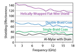
A: Standard coaxial cable has a braided or solid shield to prevent RF energy from radiating outward from the cable or external RF energy from reaching into the cable. The ability of the cable to provide such shielding is a function of the type and density of the braiding or solid conductor, as well as the frequency. Tighter or more advanced braiding provides greater attenuation and less leakage at a given frequency, as seen in Figure 1.
In general, for standard coaxial cables, better shielding comes at a cost; lower-cost cables with looser braiding allow more RF to penetrate the shield in either direction. (In fact, there have been many cases of “counterfeit” coaxial cable getting into a supply chain, with the result that the shielding is ineffective and the product performance is compromised.)
Q: So all that’s needed here is some cheaper coaxial cable that leaks a lot of RF? That would be ironic: cheaper coaxial cable is actually better than the “good stuff” for this application!
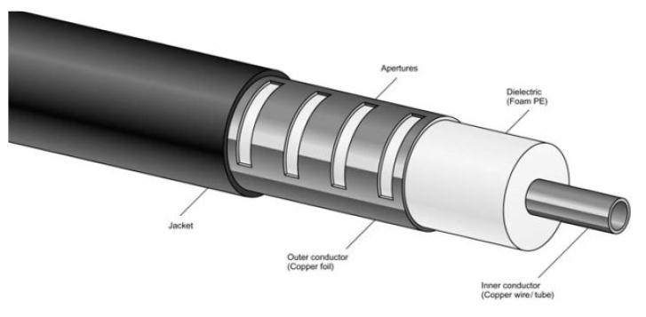
A: No, it’s not that simple. The shielding of the coaxial cable must have carefully dimensioned slots or openings for the frequencies of interest, so a known amount of RF energy leaks out per length, as seen in one possibility in Figure 2.
Q: That doesn’t seem like a big deal, but are there other issues?
A: There are always issues when designing in the RF world. Several technologies have been developed to manufacture these apertures, from loose braid to corrugated and milled leaky cables, and finally to slotted radiating cables.
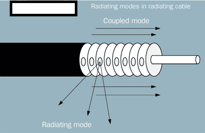
When the apertures or slots are spaced close together relative to a wavelength, the cable is a surface wave antenna and performs in coupled mode. When the slots are spaced roughly a wavelength apart, the cable will operate in radiating mode. The geometries of coupled-mode and radiating-mode radiation are shown in Figure 3.
Q: What are the implications of these modes?
A: Coupled-mode radiation is a type of surface wave. Surface waves have a power flow that runs parallel to the cable axis. In free space, very little energy leaves the immediate vicinity of the cable. In practical environments, the fields are reflected and diffracted, and provide good coverage within a region roughly 20 feet around the cable.
In contrast, when the slots are cut to ensure an in-phase addition of all apertures, the cable is then a radiating-mode cable. Such cables are more efficient than coupled-mode cables because they direct energy perpendicular to the cable axis. Radiating-mode cables exhibit a stronger frequency dependence than coupled-mode cables, but they still can be designed for broadband applications.
Q: What figure of merit is used to characterize the performance of the leaky cable?
A: Coupling loss is the most important performance specification for radiating cable, and it is defined as the ratio in decibels (dB) of power received at a half-wave dipole located a fixed distance from the cable to the power inside the cable.
Coupling loss varies widely along the cable length, moving parallel to the cable. The most common measure is the 50% coupling loss, meaning the loss exceeded by 50% of the sample points. Typical values of 50% coupling loss range from 50 dB to 80 dB for a distance of 20 feet (6 meters) from the cable. Another common measure is the 95% coupling loss.
Coupling-loss specifications can be misleading because there is no universal standard for measuring such losses. One popular manufacturer uses a distance of 6 meters, but IEC 1196-4 specifies a distance of 1.5 meters. Some manufacturers use 50% coupling loss while others use 95% coupling loss.
Q: Is coupling loss the only consideration?
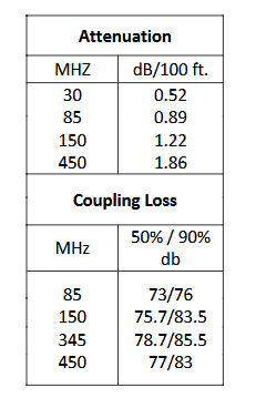
A: No. As with all cables, there is also attenuation along the cable, and coupling loss does not include the attenuation of the cable. Like conventional coaxial cables, the radiating cable’s attenuation (in dB/100 feet) increases with frequency. However, unlike conventional cables, radiating-cable attenuation varies with distance from the mounting structure. Specifications for one brand of cable, designed for operation up to 500 MHz, are shown in Figure 4.
Q: Does a leaky coaxial cable look like conventional cable?
A: It could, in theory, but usually doesn’t. The reason is that these cables are used in harsh areas, yet must be mounted along the wall “in the open” and unprotected by metal conduits. As a result, the cabling is several inches thick with its protective covering and is more difficult to manage and install. It has to be delivered, unspooled, and then hoisted onto the wall brackets or retention clips. Its size and weight require careful manipulation and special machinery to ensure an effective and safe installation. Both 50-Ω and 75- Ω cables are used, and the choice depends on the system design.
More on the leaky cable
Q: What else is interesting about this cable?
A: There is a tradeoff between its attenuation and coupling loss. One vendor achieves this by using isolated overlapping shields that are separated by a thin polyethylene interlayer. The coupling mechanism between the inner and outer shields provides a controlled RF coverage.
There are also special considerations related to the outer insulation. These cables must meet UL and other standards for non-flammability, and for not emitting noxious fumes if they begin to smoke due to a fire in their enclosed space (for this reason, they often use a low-smoke, non-halogen polyolefin jacket). Here again, counterfeit cables can be a problem; there are documented cases of substandard cables getting into the supply chain (also happens with in-wall Ethernet cables) that, in some cases, required all the installed cabling to be ripped out and replaced!
Note that the coaxial cable also carries DC power to amplifiers down the line. This is a standard “phantom power” technique that has been used for many years in applications ranging from large commercial installations to consumer very small aperture satellite (VSAT) dishes for consumer TV and Internet access.
Q: What else about cable installation issues?
A: Unlike conventional, fully shielded coaxial cable, which can be looped and allows for flexible routing, this leaky cable must be installed as relatively straight lines with a little bit of slack. Vendors provide detailed installation guidelines as to the proper brackets and hangers to use; spacing and distance from the wall are also factors. Adding to the installation challenge is that many of the installations are retrofit upgrades to older subways, so the work area is very constrained, crowded, and hazardous.
Q: Does the cable use conventional coaxial connectors?
A: The operating environment of these cables is relentlessly harsh, hot, humid, and dirty, with relentless vibration. The connectors must be larger, ruggedized, with solid locking, resistant to unintentional abuse (and maybe some intentional), and difficult to splice or fix “on site”. The installation is often done at odd hours due to existing vehicular traffic, surrounded by many operational hazards.
Q: Are there any other non-obvious considerations?
A: There are many. For example, a subway car is effectively a shielded can, so leaky signals from the nearby coaxial cable would not be able to penetrate the car if the cable were placed at an arbitrary height. Instead, the cable must be placed at the middle of the subway-car window height, or its effectiveness will be greatly reduced.
What else does it take?
Q: What are the elements of a complete system?
A: As you would expect, a complete system is much more than a transmitter, receiver, and amplifier plus a leaky coaxial cable. Among the parts are:
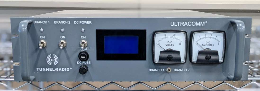
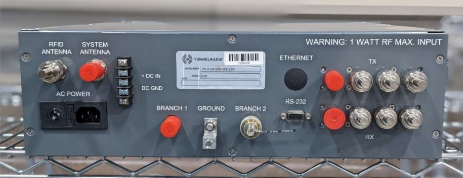
- Base Interface Unit (also called the Head Unit): the communications bridge between surface and underground radio systems; one example is shown in Figure 5. Latest-generation units offer remote top-side access for checking system performance, operational statistics, advanced diagnostics, system test, and many other features.
- Lightning Suppressor: Protects underground components from lightning strikes, a very serious consideration.
- Leaky Coaxial Cable: Carries radio signals to and from underground areas, providing radio coverage wherever present.
- Amplifier: Boosts weak radio signals back up to proper levels.
- Splice Box: Joins two pieces of leaky feeder cable together.
- Splitter: Allows establishment of a new branch of leaky feeder cable by going “off” the linear path of the main feeder cable.
- Terminal Antenna: Terminates leaky feeder while optionally extending radio coverage (you cannot leave a coaxial cable unterminated), while the antenna allows the signal to reach a little further if needed.
- Termination Unit: Properly caps a leaky feeder endpoint if no antenna is needed.
- DC Power Supply: Provide additional DC power to extend the leaky feeder system, and also includes batteries for backup power.
Conclusion
Underground tunnel, subway, and mine wireless connectivity are no longer luxuries; they are mandated by various agencies as well as user expectations. Designers can solve the problem using a mesh array of antennas, leaky coaxial cables, or a combination of both. These are not simple “plug and play” installations: the combination of RF characteristics, waveguide and cable attenuation, and many other factors, along with a harsh operating environment and the safety role of many of these systems, brings many design and installation challenges.
References
Radiating Cables, Times Microwave Systems
Radiating Cable: The Answer to the Confined-Space Communications Challenge, Tunnel Radio
On the Right PATH, , Times Microwave Systems
All-in-One Digital Leaky Feeder System, Tunnel Radio
ULTRACOMM Distributed Antenna System, Tunnel Radio
ULTRACOMM System Manual, Tunnel Radio
Challenges of Underground Transportation Wireless Coverage, American Tower
Underground Tunnel Communication Innovations Whitepaper, Innovative Wireless Technologies (IWT)
Wireless Communication in Tunnels, ResearchGate
Leaky Cables, Imperial College/UK
Leaky cables are a good thing, Urgent Communications/Informa
Related EEWorld Online content
Getting one wire to do more, Part 3 – Powering the antenna LNA
Microwave/Millimeter Wave interconnects, Part 1: Coaxial cables
Microwave/Millimeter Wave interconnects, Part 2: Connectors and cable assemblies
Coaxial cable myths and misunderstandings