
Beyond the use of optical frequency combs as precision clock sources in the optical region, researchers have developed a way to link the outstanding optical-clock performance to the creation of a high-stability, low-jitter oscillator source for millimeter-wave (mmWave) RF systems beginning at around 10 GHz and higher frequencies. This section will look at why this is needed and how it can be done using an OFC.
Q: What is a key factor in high-performance mmWave systems?
A: The controlling frequency source for the system’s local or other oscillators is critical. While absolute nominal accuracy is important, small static errors in that signal can be accommodated by use of a phase-lock loop (PLL) or other scheme.
More challenging is phase jitter, the minute and unpredictable variations of the oscillator phase (and thus also frequency) around the nominal value, which degrades performance. It has several causes, with the predominant one usually being thermally induced random motion of atoms; there are other deep physics causes as well.
Q: How is the mmWave oscillator frequency developed?
A: One widely used way is to generate a microwave carrier is to begin with a high-performance crystal-based oscillator at a lower frequency, typically in the tens of megahertz maximum, as it is not possible to use a crystal directly above that frequency range.
Q: Does this solve the jitter problem?
A: No, but it changes it. The compounding problem occurs when the lower-frequency crystal output is up-converted to the desired frequency, and an action that requires multiplying it by a factor of ten or more using a special circuit and filters.
Q: Again, what’s the problem here?
A: Up conversion inherently multiplies the phase noise of the crystal along with its fundamental, so the resultant oscillation in the gigahertz range now has far more phase noise than the fundamental had.
Q: How do OFCs help with this problem?
A: In a counterintuitive turn, the solution is to use an OFC and somehow down-convert its output, bringing it down to the desired GHz-range value. The down-conversion process actually shrinks the OFC phase noise by the down-conversion “multiplication” factor.
Q: Is this easy to do?
A: It depends on what you mean by “easy.” Nothing is easy in the optical, GHz, or related world, and the challenges are in both the concept and the details of its execution.
Q: With the right arrangement, what sort of down-conversion factor is possible?
A: The down-conversion ratio can be as high as six orders of magnitude, thus bringing the optical frequencies down to RF.
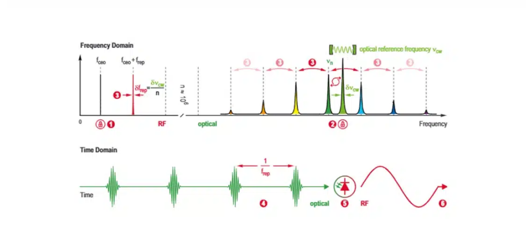
Q: How is this achieved?
A: In very simplistic terms, it is analogous to using a mechanical gear train to reduce motor speed. The OFC output rate is “pinned” (held constant) at two spectrum points and locked to an external laser reference output. The locking action results in a dispersion of new frequencies, all the way down to the gigahertz range, as shown in Figure 1:
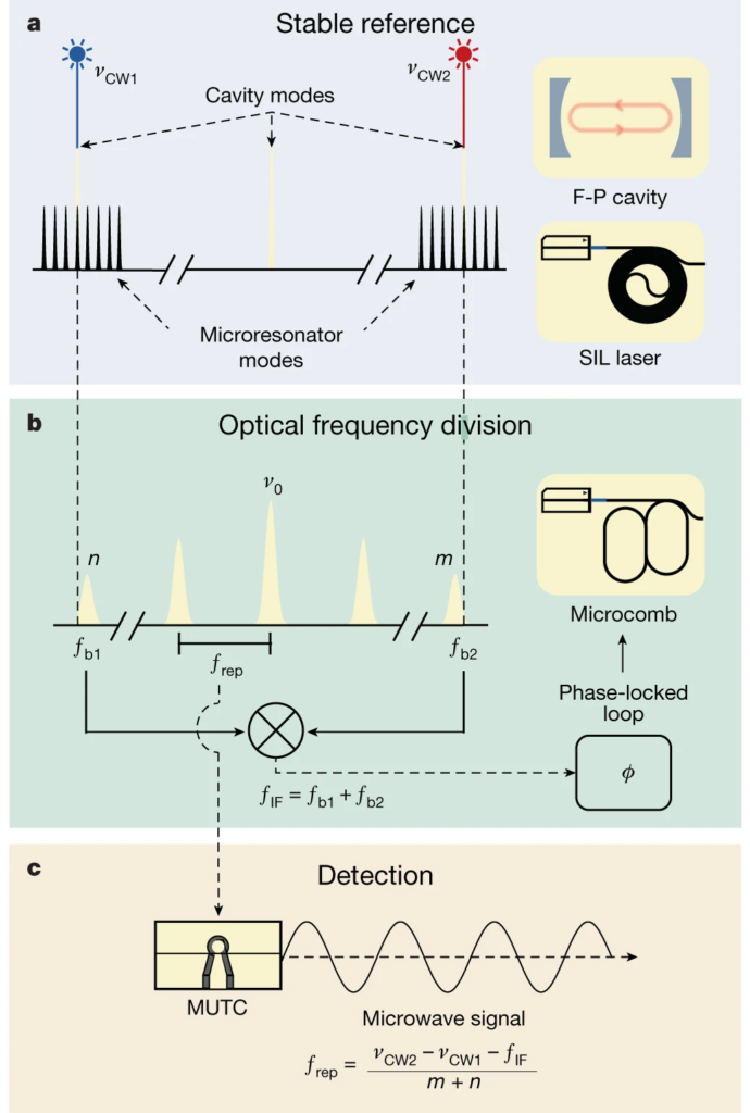
Q: What hardware is needed to make this happen?
A: This is not an intuitive down-conversion scheme, as seen in the conceptual block diagram of Figure 2:
Q: That really doesn’t seem so complicated, but what’s the reality?
A: Figure 3 shows a deeper dive into the physical implementation, and there is an even more detailed perspective in the full schematic diagram, of course (not shown).

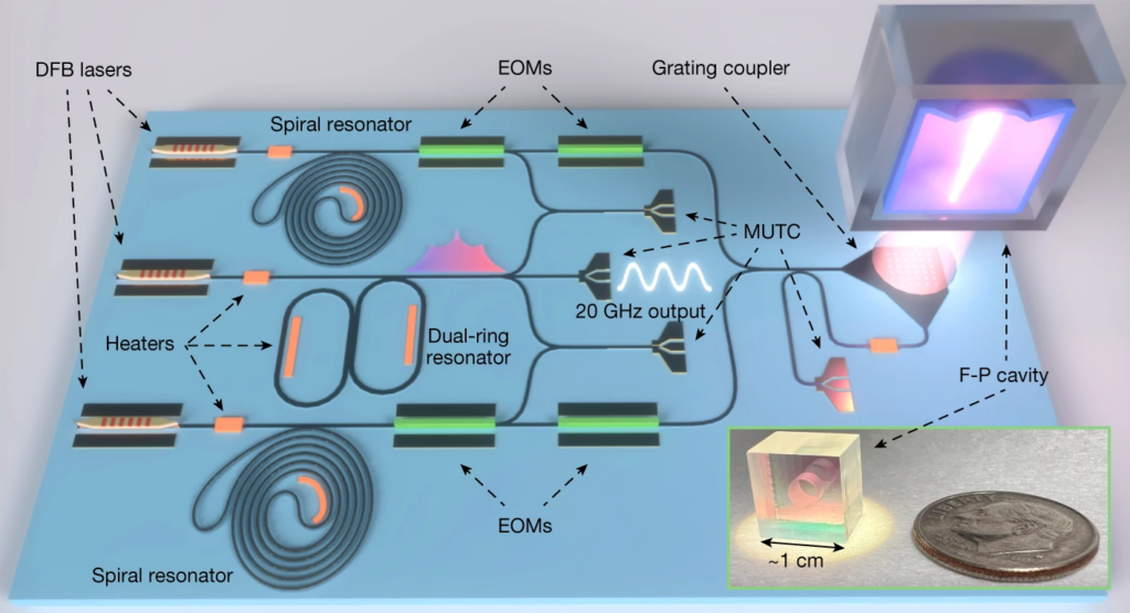
Q: Is this system available on a single or several electro-optical devices, similar to electronic ICs?
A: At present, this is not implemented as a single-chip device or even as a system with just a few discrete optical components; many of the needed precision functions are only available on individual substrates. A complete high-performance system takes a rack-sized chassis fitting in a single-height bay.
However, there has been significant progress on putting multiple functional locks onto individual substrates, so it wouldn’t be surprising to see a monolithic (or nearly so) device within a decade or perhaps just a few years, as shown in Figure 4:
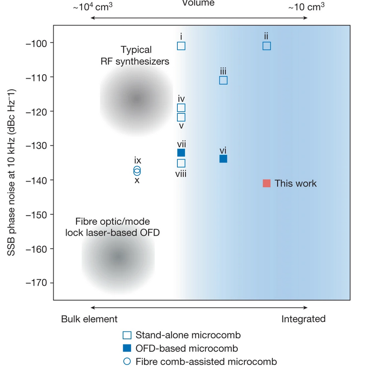
Q: What sort of performance can such a system deliver?
A: There are lots of numbers and perspectives to consider, and testing these systems at these levels of performance to assess their capabilities is as much of a challenge as fabricating them. It’s the classic metrology dilemma: how do you test a precision device? How do you validate the testing arrangement itself?
One project test result shows that for a 10-GHz carrier, the phase noise is −102 dBc/Hz at 100 Hz offset and decreases to −141 dBc/Hz at 10 kHz offset. Another characterization compares this performance to that of other available techniques (Figure 5).
Conclusion
The blending of, and synergism between, the historically separated classical RF and optical-band functions and components is occurring at a rapid rate due to the aggressive needs of the signal and data communities. There’s been impressive progress in theory, analysis, modeling, real components, and systems. Highly integrated on-chip photonics is getting a lot of attention, and while much of this is being driven by data center needs, there are many “spillover” benefits as well beyond that area.
References
[1] 20 years of developments in optical frequency comb technology and applications, Communications Physics/Nature[2] Frequency comb, Wikipedia
[3] Frequency Combs, RP Photonics AG
[4] Fundamentals of frequency combs: What they are and how they work, NIST
[5] Optical Frequency Combs, NIST
[6] Optical and microwave metrology, NIST
[7] Ultrastable Photonic Microwave Oscillators: Purity Verified, Microwave Journal
[8] Photonic chip-based low-noise microwave oscillator, Nature/Springer
[9] Compact and ultrastable photonic microwave oscillator, Optics Letters
[10] Photonic Microwave Sources Divide Noise and Shift Paradigms, Photonics Spectra
[11] A chip-integrated comb-based microwave oscillator, via Arvix
[12] Compact and ultrastable photonic microwave oscillator, ResearchGate
[13] Photonic Microwave Sources Divide Noise and Shift Paradigms, Photonics Spectra
[14] Optical Frequency Combs for Low Phase Noise Microwave Generation, URSI
[15] Integrated optical frequency division for microwave and mmWave generation, Nature
[16] Reaching Unprecedented Sensitivity in Cross-Spectrum Phase Noise Characterization, Menlo Systems
[17] Ultrastable Photonic Microwave Oscillators: Purity Verified, Menlo Systems
Related EEWorld Online content
Review: Tekbox TBCG4 harmonic comb generator
Review: Picotest J2150B comb injector
Lasers, optics, electronics and more yield terahertz sources, Part 3 – Infrared lasers and plasma
Understanding electro-optic modulation