
Oscillators are critical components in aerospace and defense systems, ranging from communication satellites to portable tactical radios and from ground-based RADAR to the GPS systems in smart ordinance. This article provides a brief overview of several key oscillator specifications, beginning with the basics.
Frequency tolerance, also called initial accuracy, is one of the most basic oscillator specifications. It’s the frequency error of the device as delivered, typically in parts-per-million (ppm) at room temperature (usually 25 °C).
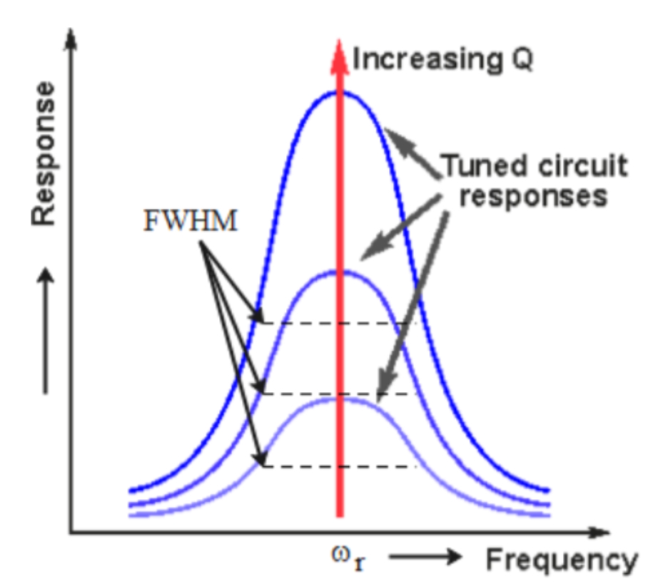
The Q (quality factor) of an oscillator is defined as the ratio of the resonant frequency (FR) and the full-width at half-maximum (FWHM), or FR/FWHM (Figure 1). It’s a dimensionless parameter and defines how well the device stores energy relative to cycle-by-cycle losses.
In general, a higher Q indicates better performance, including better frequency stability and signal purity. Crystal devices have high Qs, usually between 10,000 and 100,000, while the Qs of MEMS oscillators range from 1,000 to 5,000.
Load Capacitance (CL) is the total external capacitance for which the oscillator circuit is designed. It applies to crystal oscillators with typical values ranging from 6 to 20 pF. If the load does not match the crystal’s specs, the frequency shifts. Because the circuitry in a MEMS oscillator is self-contained, CL is not a factor.
Time, temperature, and voltage
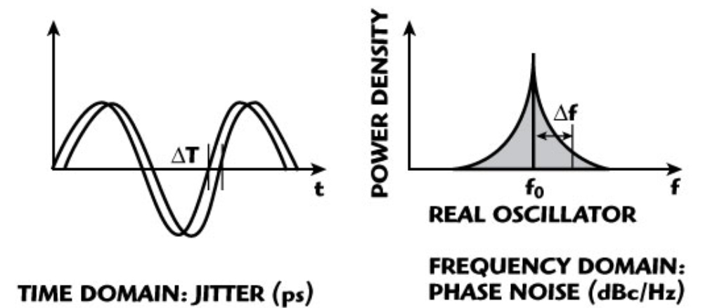
Phase noise and jitter are tiny, fast, random wobbles in the signal that measure short-term stability. While very small, these frequency changes can disrupt system operation. Jitter deals with small fractions of a second. High jitter corrupts data in high-speed processors and mangles signals in advanced communication systems.
Phase noise is measured in terms of decibels relative to the carrier per Hz (dBc/Hz). This measures how much weaker the noise is compared to the main frequency signal. It’s measured at specific offset frequencies and is mathematically related to time jitter in picoseconds (Figure 2).
Crystal oscillators more quickly reach the initial set-point frequency and can reach ±1 ppm accuracy, often within 1.5 ms. MEMS-based devices start slower and can take up to 250 ms to reach their initial set-point frequency with ±1 ppm accuracy.
Aging is the slow, natural drift in frequency over a long period. It applies to all oscillators. Specifications include maximum drift per year or per day, like ±3 ppm/year or ±3 ppm/day.
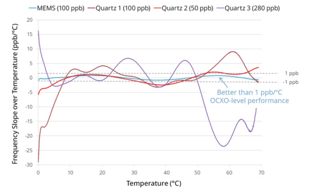
Temperature stability (dF/dT) quantifies the maximum frequency change over the specified operating temperature range. Some devices like temperature-compensated oscillators (TCXOs) and oven-controlled crystal oscillators (OCXOs) can provide tighter dF/dT specs. A typical uncompensated MEMS oscillator has worse raw, uncompensated temperature stability than a quartz crystal oscillator, but many MEMS units use active digital compensation to match or exceed standard crystal stability (Figure 3).
Voltage coefficient (ppm/V) measures how much the frequency shifts when the oscillator input voltage changes. A specification like ±0.5 ppm/V is not unusual, but it’s too loose for advanced communication infrastructure, satellite navigation, or precision measurements requiring strict ppb accuracy.
Total frequency stability
When designing oscillators into aerospace and defense systems, the specified total frequency stability (F_stab or STAB in data sheets) is an important consideration. It quantifies the oscillator’s frequency variation overall operating conditions. This composite metric combines initial tolerance, temperature drift, supply voltage changes, output load shifts, and long-term aging.
STAB is a vital metric because it defines an oscillator’s maximum frequency deviation across real-world variables like temperature, voltage, load changes, and aging. It ensures system reliability, precise timing, and signal integrity.
Typical STABs for temperature-compensated crystal oscillators (TCXOs) range from ± 0.1 ppm to ± 2.5 ppm, oven-controlled crystal oscillators (OCXOs) deliver ultra-tight performance from ± 0.1 ppb to ± 100 ppb, and standard MEMS oscillators achieve ± 10 ppm to ± 50 ppm, with some precision MEMS designs reaching down to ± 0.5 ppm.
Holdover is important in many aerospace and defense applications and quantifies the maximum accumulated time error or phase drift a device can produce when it loses its primary external reference signal (like GNSS/GPS) and relies solely on its internal free-running frequency. A typical value is ± 1.5 μs over 24 hours. Not all oscillators have a guaranteed holdover specification.
CSACs the ultimate SWAP?
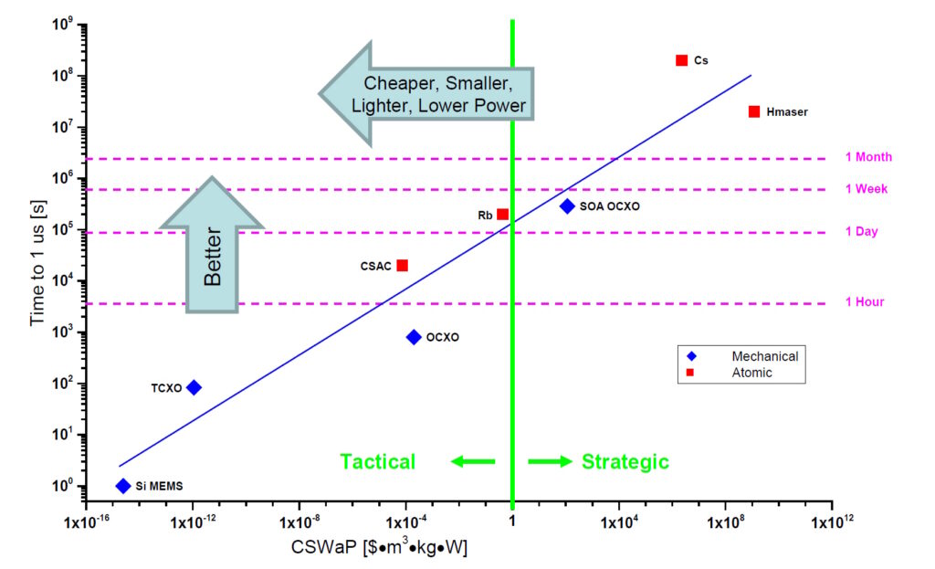
Size, weight, and power SWaP requirements vary widely based on tactical military radios, drones, and smartphones, versus strategic applications like fixed radar sites, satellite stations, and global communication networks.
When the minimum SWaP must be achieved at (almost) any cost, designers can turn to a chip-scale atomic clock (CSAC). Minimum size and weight contribute to superior shock and vibration performance. Reduced power requirements can extend the runtimes of portable systems (Figure 4).
References
Aerospace and Defense MEMS Oscillators, Microchip
Clock Oscillator Application Notes, ECS
Crystal Oscillator Design Guide, NXP
The 2 Most Important Qualities of an Oven Controlled Crystal Oscillator (OCXO), Bliley
The 8 Most Important (and Fundamental) Oscillator Parameters, SiTime
Oscillator key parameters and specifications, Texas Instruments
Oscillator Parameters, HamSCI
Phase-Locked Loop (PLL) Fundamentals, Analog Devices
Quality (Q) Factor: Equations and Applications, Allelco
Timing Technologies for Missile Defense — Quartz, MEMS, or Atomic?, SiTime
To evaluate the stability of the crystal oscillator, look at these 5 items, YXC
Understand Crystal Oscillator Parameters to Optimize Component Selection, DigiKey
What is the 10 most important parameters of crystal oscillator?, Dynamic Engineering
Related EEWorld Online content
Getting the most out of bare die: thermal optimization, custom layouts, and reliability qualification
Eclipse Foundation pushes open source deeper into safety-critical embedded systems
MIL-STD-1553B alive and well: part 1
What are the different types of wearable military connectors?
What sensors are needed to fly hypersonic missiles?