
Vibration and temperature alter the physical structures of timing devices. That causes clock signals to drift or become noisy. Environmental factors related to vibration and temperature don’t necessarily happen in isolation. Combined environmental stress can be a major factor affecting timing performance in aerospace designs.
Different types of devices don’t react the same, but in every case, bad timing signals can disrupt the operation of systems and corrupt data, causing errors. Temperature variations shift resonant frequencies, while simultaneous vibration induces mechanical stress. The combination degrades phase noise and increases jitter, potentially leading to permanent frequency drift or data errors.
Crystal-cut matters
Designers can choose from AT-cut or SC-cut crystals. “AT” is an arbitrary commercial designation for a specifically oriented resonator cut and does not stand for a specific acronym. Other arbitrary crystal cut designations include BT, CT, and DT. They are suited to different frequency ranges and offer different degrees of temperature stability.
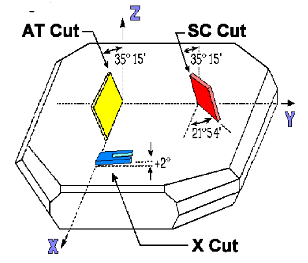
On the other hand, a stress-compensated (SC) cut crystal minimizes frequency deviations across wide temperature ranges (Figure 1). The SC-cut produces devices that are less prone to vibration-induced frequency modulation.
SC-cut crystals have high Q factors and are less sensitive to temperature variations. SC-cut crystals can operate effectively from -20 to +200 °C, compared to -10 to +60 °C for typical AT-cut crystals. SC-cut device performance varies ±0.3 ppm over temperature, while the AT-cut varies ±10 ppm.
MEMs, BAWs, and SAWs
Micro-electro-mechanical systems (MEMS) timing devices can replace traditional quartz crystals in some applications. Options include electrostatic (capacitive) and piezoelectric. Capacitive resonators use electrostatic force to excite a silicon structure into physical oscillation. The varying capacitance between the moving resonator and fixed electrodes can be used to generate a precise clock frequency.
MEMS resonators are smaller and thousands of times lighter than comparable crystal resonators. That means MEMS devices are highly robust in the presence of shock and vibration. The g-sensitivity of MEMS oscillators can range from 0.004 ppb/g to 0.5 ppb/g, on a par with the best crystal devices.
Silicon has a strong, nonlinear change in stiffness as temperatures shift. That makes MEMS resonators sensitive to temperature changes. Properly designed, MEMS oscillators can achieve a frequency stability ranging from ±0.05 to ±20 ppm across extended temperature ranges, like -55 to +125 °C.
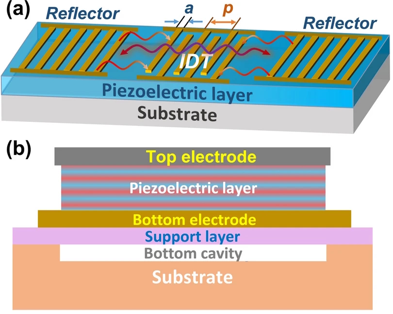
Surface and bulk acoustic wave (SAW/BAW) devices are based on piezoelectric MEMS structures (Figure 2). Standard SAWs have a temperature coefficient of frequency (TCF) of -35 to -45 ppm/°C, resulting in significant frequency drift. BAW devices are inherently more stable, typically exhibiting drifts of -17 to -25 ppm/°C, with advanced variants reducing drift to nearly zero.
BAW resonators can achieve frequency stabilities up to three times higher than traditional quartz crystals under mechanical shock and vibration. SAW devices are more susceptible to high-amplitude physical vibrations depending on their packaging, sometimes seeing transient frequency shifts or performance degradation if the surface interdigital transducers are stressed.
Getting control
Various mechanical isolation techniques can be used to minimize the impact of vibration, but vibration can’t be eliminated. In overall system designs, the temperature of timing devices is more easily controlled than the vibration environment.
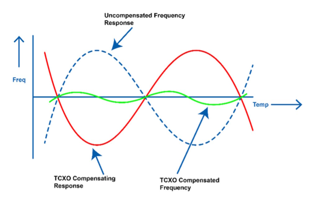
Active designs like temperature-compensated crystal oscillators (TCXOs) or oven-controlled crystal oscillators (OCXOs) are used to improve temperature performance. For example, a TCXO applies an inverse signal that almost perfectly matches the error caused by changes in temperature. In Figure 3, the green line represents the sum of the solid red and blue dotted lines and has minimal frequency drift over temperature.
Summary
Crystal, BAW, and SAW timing devices generally have a negative temperature coefficient of frequency. They are also subject, in varying degrees, to generating timing errors when exposed to heavy shock and vibration. The combination of high temperature and high shock and vibration can degrade phase noise and increase jitter, potentially leading to permanent frequency drift or data errors.
References
Combined Temperature and Vibration Testing for Wire Bond Interconnections in Harsh Environment Electronics, Journal of Microelectronics and Electronic Packaging
High Temperature, Vibration & Altitude: What Aerospace Demands from Silver Plating, Sargam
MEMS vs Quartz Oscillators: Which One Suits Your 2026 Project?, SJK
Shock & Vibration: The Hidden Enemy of Timing Accuracy in Automotive & Aerospace Systems, Saga Components
Surface and Bulk Acoustic Wave Device Characterization, Zurich Instruments
Temperature and Vibration Stress Testing for Aerospace and Defense Applications, TUV SUD
Temperature Over Vibration: Combined Environment Compliance Testing, Applus+ Keystone
The Evolution and Future of Precision Timing, SiTime
The Impact of Temperature Coefficients on SC-Cut Crystals for High-Precision Applications, Dynamic Engineers
Too hot – too shaky? Thermal testing and vibration control testing come to the rescue of electronic systems, Siemens
Related EEWorld Online content
What’s different about electronics for hypersonic flight?
Electronics that operate in extreme heat to 800°C
Why are cryogenic microwave power measurements important for quantum computing?
Electronics that operate in cryogenic cold
What are the environmental needs for electronics on a moon base?