
How VC MEMS accelerometers, angular rate sensors, and 6DoF configurations support motion studies
Test articles rarely move in only one way. A vehicle body pitches, rolls, shifts, settles, and responds to input over time. An aircraft component may vibrate under aerodynamic loading while also moving through slower structural modes. A structure may tilt or deflect under load before higher-frequency vibration becomes the main focus of analysis.
For test engineers, vibration data can be essential, but it may not explain the full response. Many tests require measurements that capture not only vibration, but also low-frequency motion, static acceleration, tilt, rotation, and multi-axis behavior.
MEMS-based sensors are well suited to that broader measurement need. Variable capacitance MEMS accelerometers measure linear acceleration, including vibration, static acceleration, and low-frequency acceleration down to DC. MEMS-based angular rate sensors add rotational measurement around the X, Y, and Z axes. When these measurements are combined, engineers can evaluate motion in six degrees of freedom, including both translation and rotation.
How VC MEMS accelerometers work
Variable capacitance MEMS accelerometers are useful in motion studies because they can measure acceleration down to DC, or 0 Hz. In practical terms, they can capture acceleration that is constant, slowly changing, or below the frequency range typically associated with dynamic vibration measurement.
That DC response also allows the accelerometer to respond to gravity. When the sensor rotates relative to gravity, the output changes. This makes VC MEMS accelerometers useful for tests involving tilt, orientation, static acceleration, long-duration motion, and vibration at the lower end of the frequency range.
Inside a VC MEMS accelerometer, small MEMS structures move in response to acceleration. In a variable capacitance design, capacitance changes as the distance between conductive surfaces changes. The sensor detects that capacitance change and converts it into an electrical output proportional to acceleration.
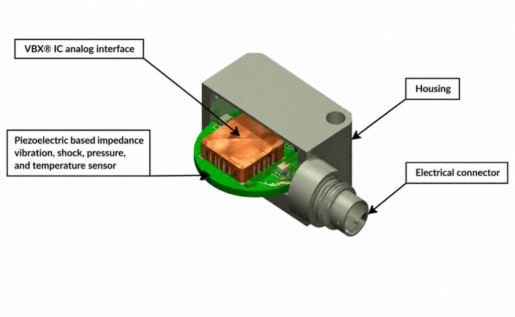
In practice, the right VC MEMS accelerometer depends on the test environment, signal requirements, and installation constraints.
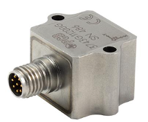
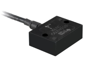
For applications that require compact, low-frequency triaxial measurement, the PCB 3700 Series VC MEMS accelerometers include options such as Models 3743G and 3753A. Across the series, DC response, rugged packaging, and practical output configurations help test teams capture vibration, static acceleration, and low-frequency motion in demanding automotive and aerospace environments.
For more information on DC-response accelerometers for low-frequency vibration, motion, and tilt, explore variable capacitance MEMS accelerometers.
Why rotational measurement needs angular rate sensors
A test article may translate along an axis while also rotating around it. It may pitch forward, roll side to side, or yaw as it responds to road input, aerodynamic forces, impact, handling loads, or structural movement.
Angular rate sensors are used to capture that rotational motion. Rather than measuring acceleration along an axis, they measure the rate of rotation around an axis. In a triaxial angular rate sensor, that means rotational data around the X, Y, and Z axes, commonly associated with pitch, roll, and yaw.
Where 6DoF fits
In real test environments, linear and rotational behavior often overlap. A VC MEMS accelerometer can capture acceleration, vibration, tilt, and changes in orientation relative to gravity. An angular rate sensor adds the rotational data needed to understand pitch, roll, and yaw during the test.
Six degrees of freedom measurement brings linear and rotational data together. A 6DoF configuration combines three axes of linear acceleration with three axes of rotational measurement. The accelerometer captures translation along X, Y, and Z. The angular rate sensor captures rotation around those axes. Together, they help engineers evaluate how a test article moves through the test environment, rather than interpreting linear or rotational behavior in isolation.
This can be especially useful in automotive, aerospace, and defense testing, where motion is rarely confined to one direction and sensor space may be limited. In a compact MEMS-based setup, engineers can measure vibration, low-frequency acceleration, tilt, rotation, and multi-axis response without adding more size or complexity than the test can support.
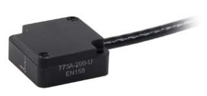
For applications that require both measurements, PCB’s Endevco product line offers a compact 6DoF measurement solution by pairing the Endevco Model 773A triaxial DC-response VC MEMS accelerometer with the Endevco Model 7330 triaxial angular rate sensor. The accelerometer captures three axes of linear acceleration, while the angular rate sensor captures rotational motion associated with pitch, roll, and yaw.
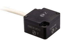
Learn more about angular rate and 6DoF sensors for rotational measurement, pitch, roll, yaw, and combined motion studies.
Getting the signal to the measurement system
Choosing the right sensor is not only about range, frequency response, or package size. The signal still has to make it from the sensor to the measurement system.
That path may include cables, connectors, instrumentation, grounding issues, and electrical noise. Output configuration directly affects how well the signal is carried through the setup.
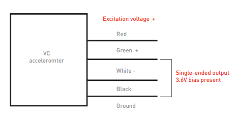
A single-ended measurement uses one signal output measured relative to ground. This approach can be useful when instrumentation options are limited, but it requires careful attention to grounding, bias, zero offset, cable routing, and environmental effects.
A differential measurement uses two signal lines, and the measurement system reads the difference between them. Electrical interference is often picked up similarly on both lines, so a differential input can reject much of that shared noise while preserving the acceleration signal. Differential output is often preferred when low-level signals must travel through longer cables or electrically noisy test environments.
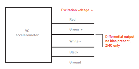
For DC-responding accelerometers, zero measurand output, or ZMO, is another setup detail to get right. ZMO is the output present when the accelerometer experiences 0 g along the measurement axis. Because gravity affects the output of a DC-responding accelerometer, mounting, orientation, and zeroing all play a role in making sure the sensor captures the intended motion.
Matching the sensor to the motion
Good motion data starts with a clear understanding of what the test needs to reveal. In some cases, vibration measurement may be the primary concern. In others, the motion of interest may include low-frequency acceleration, tilt, static response, rotation, or movement across multiple axes. Choosing the right sensor configuration helps engineers capture those behaviors clearly and connect the data back to the motion being studied.
For a broader overview of test and measurement sensor options, download the PCB Test & Measurement sensor guide.
Sponsored content by PCB Piezotronics