
In industrial or transportation settings, there is a lot of equipment rotating and sliding on a variety of bearings (e.g., bearing types such as ball, sleeve, roller, and slide). These are lubricated to minimize wear, but nonetheless, wear does occur. When wear becomes excessive, vibration may increase, or equipment may grind (literally) to a complete stop. Maintenance workers must then shut down production lines and replace bearings, conveyor belts, motors, and/or other moving parts.
During the periods when the equipment is taken out of service and repairs are made, if it isn’t scheduled maintenance, it’s guaranteed that such repairs will directly cause significantly larger losses of revenue compared to losses incurred during scheduled maintenance. Production line shut downs means product isn’t fabricated and shipped out the door: Revenue is lost. Transportation service annulments (planes, trains, buses, and ships) also lead to revenue losses.
We would hope that this doesn’t occur in the midst of an important production run or while transporting vital or perishable cargo (e.g., medicine, patients, produce, airborne travelers, etc.). Otherwise, losses can be unbearable.
To mitigate these problems, we need a way to predict the future. Scheduled or preventative maintenance (PM) can help — for example, after so many hours of service, tear down the motors and power trains and rebuild. There are various software packages available to provide guidance concerning PM. Another approach can be a bit more cost-effective. Consider this approach with respect to a specific motor example. Monitor its operating temperature (with respect to the ambient temperature using thermistors or platinum RTDs) and track it over time.
If you see the motor temperature slowly rising day by day, you could assume any of the bearings in the power train are exhibiting wear (a likely cause), or there is excessive current draw (shorted winding or a shunt to ground), which causes more internal heating. That current draw issue points immediately to the need for additional sensors: If you add a current monitor on all three phases (assuming it’s a standard induction motor or a brushless DC motor), you can get some very useful information that will help predict when failure will likely occur.
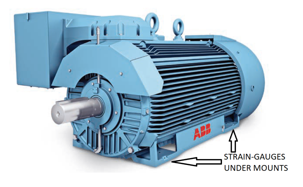
You can also install strain gauges between the motor mounting points and the equipment framework. By monitoring their output, you can tell if the mechanical load into which the motor is working is starting to develop problems. See Figure 1.

With regard to oil lubricants used internally in gearboxes and internal combustion engines (ICE), there are techniques available to monitor both the color of the oil and the amount of suspended particulates in the oil (opacity measurements). That will allow you to gauge when to change the oil and oil filter or to predict when the ICE is operating sub-optimally (e.g., gas/air mixture is wrong; oil is overheated and burnt).
For equipment whose prime mover is a vacuum motor, an air motor, an air turbine, or a steam turbine, one trouble area is leaks. You can monitor system vacuum or pressure and, similar to current and temperature monitoring, look for a slow change over time. This points to leaks in joints or gaskets. You can also use ultrasonic detectors to listen for the characteristic sound profile associated with leaks. Often, the sound is not in the audible (to humans) range, so the ultrasonic technique can prove very useful. See Figure 2 for a not entirely practical ultrasonic detector.
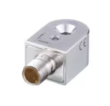
There is another useful technique that has become more practical and inexpensive. Adding vibration sensors to the ICE and electric motor housings, bearing journals, and gear boxes (as used with, e.g., conveyor belts, punch presses, milling machines, oil rigs, wind turbines, and backup generators). These sensors can be either piezoelectric (PZ) devices or integrated circuit-based accelerometers. You can buy these sensors as a packaged device with a bolt-on mounting tab (among several other mounting styles); see Figure 3.
Or you can purchase the PZ device or accelerometer IC and fabricate your own PC board and case – a good, cost-effective alternative if you’re going to build devices on the order of thousands (or more) pieces per year. Note that when IC accelerometers were first sold, they were pretty expensive. Now they are practically at the dime-a-dozen price point and can provide multi-axis monitoring, so rolling your own makes sense if the quantities needed are large enough.
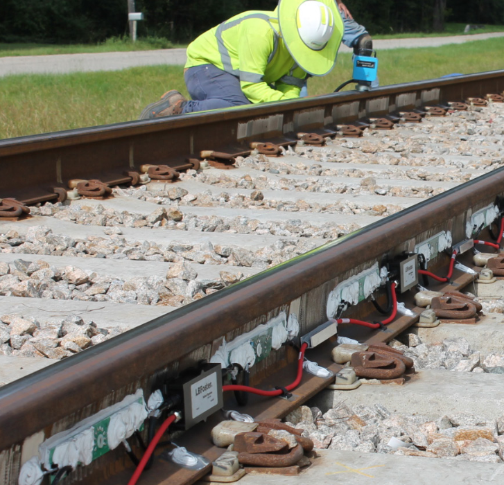
Vibration and heat sensors (typically IR sensors rather than thermistors or platinum RTDs) are also used for monitoring railroad rolling stock. The vibration detectors “listen” to the sound of the wheels rolling past and can hear stuck brake shoes, excessively worn bearings, and wheel flat spots banging against the railhead. Flat spots occur from excessive emergency brake applications, which can lock up the wheels and grind flat spots into them. See Figures 4a and 4b, which show two versions of rail-mounted vibration/wheel detectors.
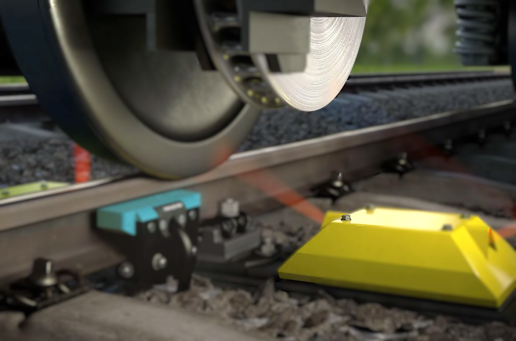
IR sensors will detect overheated bearings, axles, and brake shoes, adding a small layer of redundancy to the information you get from vibration monitoring. See Figure 4b again and Figure 5, which shows a typical hot wheel bearing/hot axle detector.
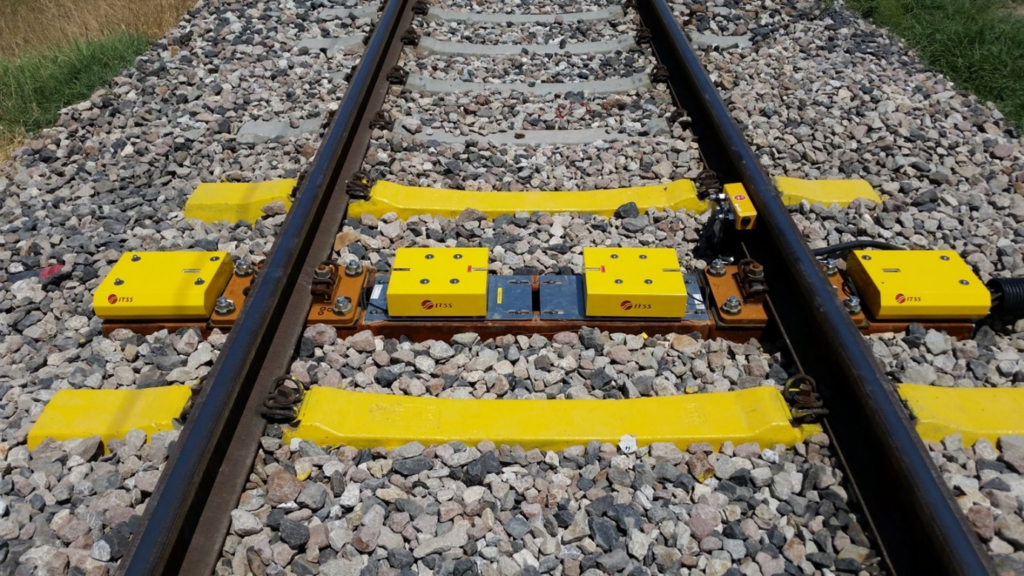
This sort of defect detector equipment is often combined with dragging equipment detectors comprised of paddles placed between and directly next to the rails. It notifies the crew of anything of any significant mass, dragging below/behind the cars, that knocks down the paddle. Figure 6 shows a typical dragging equipment detector.
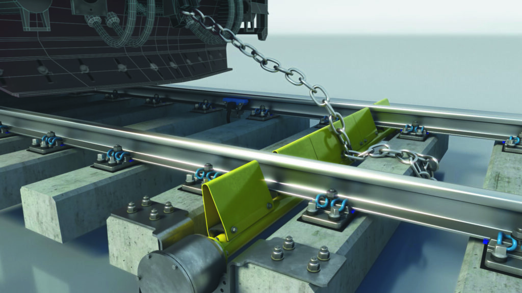
The defect detectors’ results are radioed to the train crew so they can take the appropriate action. Here’s a typical report from a passing CSX train where everything checked out OK.
And here’s a number of audio recordings of trouble from passing trains. These are available from the DefectDetector online page. These radioed reports are what the train crew hears.
Beyond these failure prediction monitoring techniques, there are a number of methods to self-monitor the electronics that reside within the control boxes associated with the sensors described above. We will push into such devices in a subsequent article.
Keep in mind that failure detection and prediction are not perfect and probably never will be. As these systems improve, the probability of a false negative (a false indication of failure) will become very small – but not zero. Recall from the movie “2001: A Space Odyssey” the AI computer system (the HAL 9000) predicted a complete com-link failure:
I’ve just picked up a fault in the AE35 unit. It’s going to go 100% failure within 72 hours.
One of the astronauts performs an EVA and pulls the AE35 com-link unit out of service. They put the unit on the bench and poke around the circuitry, trying to locate the problem, but they can’t find anything wrong. They ask HAL what the best course of action is, and HAL tells them:
I would recommend that we put the unit back in operation and let it fail. It should then be a simple matter to track down the cause.
One of the astronauts again performs an EVA to return the AE35 to service, but HAL takes some rather unorthodox action. From this, we can learn that software-based failure prediction models are not perfect. Be aware.