
Part 3: Measuring WCET in multicore systems
by Jay Thomas, Senior Director of Field Engineering, TASKING, and Gerard Vink, Industry Specialist, TASKING
In part 1 and part 2 of this article series, we established that WCET in a multicore system cannot be determined by analyzing a task in isolation. Data coupling, control coupling, and — most significantly — timing coupling all introduce execution time variability that depends on the behavior of concurrently running tasks and the state of shared hardware resources. Here in part 3 of this article series, we’ll explore a practical three-stage methodology for measuring worst-case execution time (WCET) in multicore-based systems with a focus on requirements, design, and verification.
Overview of the methodology
This methodology for assessing WCET has three stages, each suited to a different phase of the development lifecycle:
| Stage | Development Phase | Primary Technique | Purpose |
| 1 | Early (design and initial coding) | System timing requirements, Halstead metrics and static analysis | Identify high-risk code early; guide architectural decisions |
| 2 | Mid (integration and test) | Empirical dynamic analysis on target hardware | Measure actual execution times under realistic interference |
| 3 | Late (system verification) | Data and control coupling analysis | Verify all coupling points have been exercised; produce compliance evidence |
Stage 1 — Early development: static analysis and complexity metrics
The earlier in the development lifecycle a timing problem is identified, the less costly it is to resolve. Stage 1 of this methodology uses static analysis techniques to identify code that is likely to place high demands on execution time, before any target hardware is available.
Halstead complexity metrics
Halstead’s complexity metrics, derived from counts of operators and operands in the source code, provide quantitative indicators of a module’s size, complexity, and cognitive difficulty. From a timing perspective, they serve as an early warning system. Modules with high Halstead volume or effort are likely to have longer execution paths, more complex data flows, and greater sensitivity to interference.
Static analysis tools can compute Halstead metrics automatically across the codebase, allowing developers to rank modules by timing risk and prioritize their effort. Code identified as high-risk at this stage can be restructured, simplified, or partitioned before integration. Taking this step can avoid much more expensive software rework later.
Coupling and cohesion analysis
Static analysis also enables the identification of data coupling and control coupling at the code level. Tools can trace data dependencies between modules, including identifying shared variables, passed parameters, and control flags. The tools can then produce coupling maps that show which modules are coupled and through what pathways.
Two complementary design principles are relevant here. High cohesion means that a module has a single, well-defined responsibility and that all its internal elements serve that responsibility. Low coupling means that modules interact through minimal, well-defined interfaces and do not reach into each other’s internal state.
Designing software with high cohesion and low coupling minimizes the number of coupling points in the system as well as reduces the complexity of assessing each coupling point. This directly reduces the number of interference pathways that must be analyzed for WCET purposes and makes it more tractable to demonstrate that all coupling has been exercised through testing.
Standards alignment
Several safety standards reference coupling analyses as a design and verification obligation. ISO 26262 (automotive functional safety) explicitly recommends architectural designs that exhibit high cohesion and low coupling. DO-178C (airborne software) requires analysis to confirm that requirements-based testing has exercised all data and control coupling between code components. Performing coupling analysis at Stage 1 therefore contributes directly to producing the necessary standards compliance evidence.
Stage 2 — mid development: empirical dynamic analysis
As shown earlier, static analysis cannot account for timing coupling and the resulting hardware-level interference that arises from shared multicore resources. Timing coupling must be measured empirically, on real target hardware (or a sufficiently faithful virtual ECU simulator), with real tasks running concurrently.
Why empirical measurement is necessary
The fundamental reason empirical measurement is necessary is that timing coupling interference depends on runtime behaviors that cannot be predicted statically. Such behaviors include the precise overlap of task execution windows, the actual data access patterns as they compete for cache lines, and the real-time arbitration decisions of the memory controller. These factors interact in ways that are too complex to bound analytically with acceptable tightness.
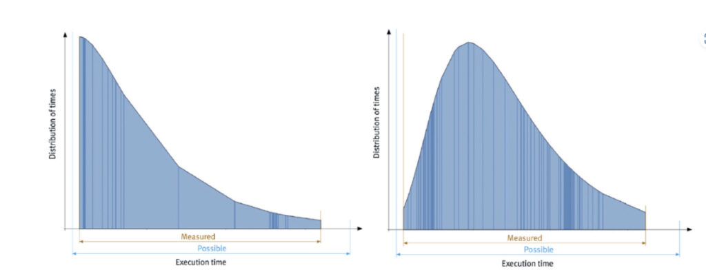
Measurement-based WCET analysis observes the system’s actual timing behavior across many iterations, accumulating execution time measurement samples that capture the distribution of interference effects. Figure 1 illustrates the impact of hidden timing coupling. The left-hand histogram shows the execution time distribution of a task running without interference. The right-hand histogram shows the same task running under multicore load. The entire distribution shifts to the right, including both the mean and the tail. This demonstrates that deriving a WCET estimate from single-task or single-core measurements would be unsound.
The iterative measurement process
Because the interference pattern varies between runs (see part 1), a single measurement pass is insufficient. The measurement process must be iterative, exploring many combinations of:
- Task start offsets to vary the degree of temporal overlap between concurrently executing tasks on different cores. Start with a clean design to limit time coupling.
- Task data sizes to probe the L1/L2 cache boundary effects demonstrated in the DEVCOM study.
- Processor configuration settings, including cache enable/disable states and core affinity assignments, to determine the impact of particular configuration choices.
- System load levels, including stress testing with maximum concurrent load on all cores so measurements align with real-world operation.
Automation is essential for the iterative measurement process. The number of combinations to explore grows rapidly with system complexity, and manual test execution is both error-prone and impractically slow. Automated test harnesses can wrap individual software modules or task functions, drive them through the required combinations, and capture timing data from hardware trace infrastructure more efficiently and accurately than if they were performed manually.
The following example demonstrates how to automate Stage 1 and 2 empirical WCET Analysis using agentic AI workflows while maintaining requirements traceability as required for certification:
- Assess: Use static analysis test tools to evaluate the system and assess software complexity, control-flow, and data and control coupling. This information helps developers identify likely timing hotspots that negatively impact WCET as well as prioritize the specific functions and task interactions that should be closely monitored during on-target, run-time measurements.
- Instrument: Have the compiler instrument relevant code modules with lightweight timing wrappers that enable function-level timing measurements without requiring manual source code modification.
- Capture: Set up and configure the hardware debugger to provide non-intrusive, on-target tracing. This will provide cycle-accurate, real-time timing data from the running system while preventing the test process from adversely affecting execution behavior or skewing the accuracy of WCET measurements.
- Automate: Use agentic AI to automate the WCET measurement workflow. This includes driving comprehensive interference scenarios, collecting and visualizing execution time histograms, and producing auditable timing evidence for certification purposes. With the right tools, developers can take the raw data collected and create a statistical distribution that can be used to check and verify against the system’s real-time timing requirements.
- Campaign: Orchestrate an entire measurement test campaign using agentic AI to manage and accelerate the iterative test process across an extensive range of scenarios and execution runs to more accurately estimate the actual WCET of the system.
Multicore WCET analysis involves many thousands of test iterations. AI-assisted automation can substantially improve efficiency while at the same time reducing the risk of human error. For example, if a particular combination of compiler options causes a build failure during an automated iteration, an AI agent can diagnose and correct the error so that the iteration completes without interrupting the analysis process. Agent actions are logged and flagged for human review, maintaining the traceability required by safety standards. With a vertically integrated development pipeline that combines compilation and debug through on-target measurement and collection of certification evidence, developers can address the full scope of Stage 1 and 2 analysis and automate many complex manual tasks to increase assessment coverage and increase confidence in the overall WCET analysis.
Stage 3 — late development: coupling coverage verification
Stage 3 of the methodology addresses the verification obligation that all coupling points in the system have been exercised by testing. This is both a standards requirement and a practical assurance measure because coupling points that have never been exercised during testing represent untested interference pathways that could produce significant timing behavior not reflected in the WCET estimate.
Data and control coupling coverage
Data coupling and control coupling coverage analysis determines, for each identified coupling point in the system, whether that coupling has been exercised by the test suite. A coupling point is considered exercised when a test case causes data to flow across the coupling (for data coupling) or causes a control decision to be influenced by the coupled component (for control coupling).
Figure 2 shows an example of a control coupling report. The report identifies 17 control couples in the analyzed file, of which 12 have been covered (71%). The breakdown by file shows which inter-module coupling relationships are fully covered, partially covered, or not covered at all, which gives the developer precise targets for additional test cases.
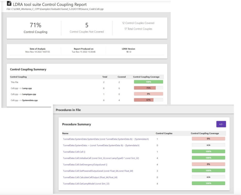
Coverage reports provided by these tools identify which couples have and have not been exercised, enabling developers to target additional test cases that address gaps in coverage. Once full coupling coverage is demonstrated, the report becomes part of the compliance evidence package.
Coupling coverage as FFI evidence
In the ISO 26262 framework, the obligation to demonstrate that safety-critical software components do not interfere with each other is expressed as Freedom from Interference (FFI). Coupling coverage analysis is a primary means by which FFI is evidenced at the software level. This is achieved by showing that all identified coupling pathways have been exercised and that the observed behavior is consistent with the system’s safety requirements.
Data coupling and control coupling coverage reports therefore serve a dual purpose. First, they are a WCET analysis input confirming that the coupling interactions relevant to timing have been tested. Second, they serve as a standalone compliance artefact for the FFI safety case.
In part 4 of this article series, we will explore ways developers can mitigate timing coupling interference by addressing root causes such as reducing contention for shared hardware resources.