
This legitimate concern has various solutions; these require insight and understanding for analysis.
Circuit designers — especially those implementing “analog” functions such as sensor front ends or power supplies — live in a world of components with specifications that will inevitably drift and change due to the passage of time (aging), active use, voltage variations, and temperature shifts. As a result, they need to take such changes into account so their end product does not go “out of spec” once in the field.
Some of these undesirable attributes can be anticipated via modeling and simulation, but many aspects have to be assessed through experience and knowledge of component specialists. There is a large and active engineering specialty devoted to the science and art of making sure systems don’t fail or have cascading problems when things go wrong, or at least fail gracefully.
Their scope is well beyond this brief article. Instead, we will look at some specific cases that may spark some thinking about the issues.
Dealing with drift and aging
There are several standard ways to accommodate the reality of temperature drift, component aging; they can be used individually or in combination:
1) Choose components with suitably tight specifications for the critical parameters related to drifts due to aging, temperature changes, and shifts in operating points. This is usually a relatively costly approach; parts with tight-enough specifications may not be offered, and even if they are, their availability may be limited.
2) Periodically invoke a calibration procedure while the product is in use. This requires at least one “golden” component, such as a voltage reference, which has superior stability over time and temperature. to be used as a standard for the calibration procedure. Again, this top-grade component may be costly or in limited supply. Also, the overall system architecture and software must include additional calibration circuitry, such as a high-resolution analog/digital converter and corresponding calibration software.
3) Use an architecture or topology in which many errors self-cancel. One way to do this is with differential circuitry where changes in both “legs” of an analog front end (AFE) track with each other and effectively cancel out the change.
For example, this is an attractive option when the input resistors of an amplifier can be placed on the same die, for example, as with the Texas Instruments INA133 difference amplifier seen in Figure 1 and R1 and R3. (Note that this amplifier was introduced in the 1990s – and it is still used in new designs!).
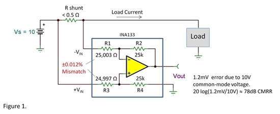
Figure 1. For best performance, the on-chip input resistors for the INA133 difference amplifier track each other despite changes in temperature and other operating conditions. (Image: Texas Instruments)
In this example, the internal resistors have a ±0.012% mismatch in their nominal 25 kΩ value. While a ±0.012% mismatch seems quite small, it is at the limit of what is acceptable for the needed level of performance and accuracy.
However, the important factor is that the two resistors track each other nearly identically across temperature and other operating variations. Thus, their differential ratio remains unchanged even if the absolute values drift, yielding a high-accuracy circuit.
Note that this is a case where the dilemma of “how much reliability and performance do you need, and what are you willing to pay for it?” is turned around. While higher reliability and performance are generally associated with higher costs, an IC with matching on-chip resistors takes less board space, is less costly, and more reliable than an IC with two external resistors.
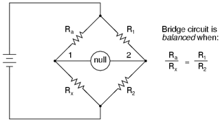
Another example of a canceling error by design is the classic Wheatstone bridge, which makes use of a ratiometric input/output relationship where component ratios rather than their absolute values are important, shown in Figure 2. It’s much easier to maintain accurate, consistent performance of such ratio relationships.
When good components start to go bad
Components that drift or age out of specifications are just one class of problem. Another issue occurs when a component is stressed to partial failure or develops an internal fault due to a manufacturing defect.
In most cases, this is a problem without any easy solution. In mission-critical or hazardous-voltage applications, the designer needs to consider the impact of potential failures and how to mitigate them or provide an extra layer of protection (these are often defined by regulatory standards).
For example, line-powered medical electronics may require isolation transformers that prevent even minuscule current flow to ground, even if there is an internal component or insulation failure.
Similarly, line-powered (not battery-powered) power tools now use enclosures that are double-insulated with no conductive parts that the user could touch. In this way, even if an internal high-voltage wire short-circuits to the case, there is no opportunity for dangerous current flow to (and through) the user, even if there is no safety-ground power wire in the AC power cord.
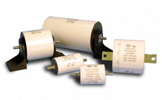
In other cases, designers can select components that are designed to recover after a partial failure or at least degrade in a benign fashion. For example, metalized polypropylene film capacitors such as the 5MPA2 family from Electronic Concepts Inc. will self-heal after a fault in the dielectric, which occurs due to high overloads or voltage transients, as seen in Figure 3.
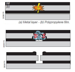
When the insulation breaks down, a short-duration, highly localized arc forms at the breakdown site, illustrated in Figure 4 (top). The intense heat generated by this arc causes the metallization in the vicinity of the arc to vaporize, shown in Figure 4 (middle), and simultaneously it re-insulates the electrodes and maintains the operation and integrity of the capacitor, see Figure 4 (bottom).
Other capacitors do not heal, but instead have what is called a “benign failure mode.” Even in the event of a short-circuit failure, for example, tantalum polymer capacitors such as the Kyocera AVX TCO series do not exhibit an undesired “transient thermal event” (arcing or intense flare-up) that may occur with manganese-dioxide (MnO2)-cathode tantalum capacitors, which can lead to combustion or fires.
Conclusion
Designers must consider the impact on performance of full or partial failure in the context of a product’s application. While a failed power-subsystem component in a smartphone does not put the user or system at risk, a short circuit in a line-operated supply might easily do so. That’s why nearly all such supplies have components for protection against over- and under-current and voltage conditions, short circuits at the load, and even thermal cutoffs in case of overtemperature conditions.
The need for protection against failure predates electronics, of course. The Westinghouse fail-safe railroad brake was developed in the late 1800s and is still used today. In this architecture, the presence of compressed air is needed to release the brakes. If the compressor, compressed-air reservoir, or air hoses fail in any way, the brakes engage and will not release.
The important question is to understand what can go wrong and with what likelihood, as well as the ripple effect of these problems. This includes outright failure as well as deviations due to temperature, aging, or other factors. Then you have to decide which problems can be tolerated to what extent, if any, and what can be done, if anything.
Analyzing possible failure modes and out-of-specification non-failure degradation modes, along with their impact on circuit and system performance, is a major subject with significant literature and experience to provide guidance. Modeling tools such as Spice, along with approaches such as Monte Carlo simulation, are enormously beneficial here; many other tools are available as well.
In the ideal or perhaps in a future world, components that fail would begin to self-heal, much as the human skin, bones, and other organs start to repair themselves in many cases, as long as the damage is modest. For now, an approximation to self-healing is only possible by using complicated schemes at a system level, such as redundant circuitry with some sort of automatic or manual switchover arrangement.
However, the challenge of devising self-healing wires, passive, and even active circuit elements is one which many university researchers are tackling. Who knows…maybe someday, individual components may initiate self-healing modes as a standard part of their design and functionality?
References
Difference Amplifiers—the need for well-matched resistors, Texas Instruments
When benign is better: fail safe capacitor technology, European Passive Components Institute
The self-healing characteristics of metallized film capacitors, European Passive Components Institute
Technical Summary and Application Guidelines, AVX
MLCC & Tantalum Interchangeability, AVX
Conductive Polymer Capacitors Basic Guidelines, AVX
New Reliability Assessment Practices for Tantalum Polymer Capacitors, Kemet Electronics Corporation, Evaluation of Polymer Counter-Electrode Tantalum Capacitors for High Reliability Airborne Applications, Kemet Electronics Corporation
Conductive Polymer Capacitors: Frequently Asked Questions (FAQs)
What is Self-healing for capacitors?, Schneider Electric
The Self-Healing Affect of Metallized Capacitors, Electronic Concepts, Inc.
New ‘Self-Healing’ Gel Makes Electronics More Flexible, University of Texas
Scientists Invent Self-healing Battery Electrode, Tech Briefs
Self-Healing Wire Insulation, Tech Briefs
Related EEWorld Online content
Wheatstone bridge, Part 1: principles and basic applications
Wheatstone bridge, Part 2: Additional considerations
The why and how of matched resistors: part 1
The why and how of matched resistors: part 2
Westinghouse and the fail-safe train air brake, Part 1: The problem
Westinghouse and the fail-safe train air brake, Part 2: The solution