
Both radio frequency (RF) and optical energy are governed by Maxwell’s equations, but they often have little else in common. RF devices are generally available up to around 100 GHz (albeit at increasing cost and fragility), where they run into barriers due to the laws of electromagnetics and limitations of solid-state materials and their performance, while optical devices use a very different component structure to do their “magic.”
Between the two regions lies the terahertz band spanning approximately 100 GHz to 10,000 GHz (0.1 THz to 10 THz). This is a region of the spectrum where there are few viable electronic or optical devices for designers, despite their longing to access that wide swath of unused and largely inaccessible bandwidth.
The reality of the RF and optical gap is intense. For the RF world, there are electronic amplifiers, switches, analog/digital and digital/analog converters, and power devices; the optical world has its more esoteric devices, such as all-optical amplifiers, lasers, Bragg gratings, Fabry–Pérot interferometers, Brillouin spectroscopy, Raman spectroscopy, Pockels cells, and more. Perhaps not surprisingly, the interposed terahertz zone has little to call its own.
Despite the existence of these two non-overlapping worlds, there has been considerable research and progress in enabling each to support the other and leverage their capabilities to enhance the other side. One good example is the optical comb, a fascinating structure with unique output that is being used to create high-performance microwave oscillators for RF applications. This FAQ will look at these combs and how they are used for this critical function.
Q: What’s an optical comb?
A: Despite its name, it is not a device for untangling knots in strings of photons or untwisting convolved, propagating optical waves. Instead, it is a somewhat esoteric and complicated laser-based arrangement for generating a continuous stream of precisely spaced optical pulses. The spacing is so near-perfect and consistent that the optical comb is in many ways superior to the classic “atomic” clock, and is even being evaluated for use as a primary time standard in place of the latest iteration of these clocks.
(Note that it is also called a frequency comb, or optical frequency comb (OFC), but those designations are not as crisp as the simpler, attention-getting term “optical comb”.)
Q: What can these optical combs be used for? Or are they just laboratory demonstrations?
A: Due to the precision of the comb output, it is already widely used as a standard for precision measurement of frequency (and thus wavelength) of optical signals and for establishing an optical frequency source.
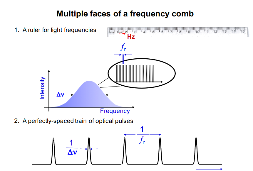
A basic frequency comb can be used as an optical ruler: If the comb frequencies are known, the frequency comb can be used to measure unknown frequencies by measuring beat notes, which reveal the difference in frequency between the unknown frequency and the comb frequencies, as depicted in Figure 1.
Optical comb history
Q: What is the history of the optical comb?
A: The development of the optical comb was not an “accidental” discovery, nor was it an obvious intuitive development or even a counterintuitive “flash.” Instead, it was the product of deep insight into optical physics and lasers, and the implications of that discipline.
Optical frequency combs began as part of the ongoing quest for optical atomic clocks. In the late 1970s, Theodor W. Hänsch originated the idea for the optical frequency-comb technique, in which ultrashort pulses of laser light create a set of precisely spaced frequency peaks that resemble the evenly spaced teeth of a hair comb. John Hall extended this research on measuring optical frequencies. Although a procedure known as the optical frequency chain had already been developed to make such measurements, it was so complex that it could be performed in only a few laboratories.
Hänsch and Hall simplified the process concept, although “simplified” is a very relative term here, of course. Their technique offered a practical way of obtaining optical frequency measurements to an accuracy of 15 digits, or one part in one quadrillion. These two were recipients of one-half of the Nobel Prize in Physics in 2005 (the other half of the prize went to Roy J. Glauber for a totally unrelated advance).
Q: What are some specifics of the actual applications of OFCs?
A: It became a long list once OFCs were available as practical, non-lab instruments. They quickly appeared in a multitude of diverse applications covering optical, atomic, molecular, and solid-state systems, including X-ray and attosecond pulse generation, coherent control in field-dependent processes, molecular fingerprinting, trace gas sensing in the oil and gas industry tests of fundamental physics with atomic clocks, calibration of atomic spectrographs, precision time/frequency transfer over fiber and free-space, arbitrary waveform measurements for optical communication, and precision ranging.
Optical clock principles
Q: So, how does an optical clock work?
A: It would be nice to be able to say that there is an easily presented and understood way to explain it, but that is not the case. In addition to a coarse qualitative explanation, there are also equations related to deep physics, including the almost trivial yet critical “comb equation.” There are several ways to generate the comb:
- Using a mode-locked laser to produce a series of optical pulses separated in time by the round-trip time of the laser cavity. The spectrum of this pulse train approximates a series of what are called Dirac delta functions separated by the repetition rate (the inverse of the round-trip time) of the laser.
- Using four-wave mixing, where intense laser lights at three frequencies combine to produce light at a fourth frequency. If the three frequencies are part of a perfectly spaced frequency comb, then the fourth frequency is mathematically required to be part of the same comb as well.
- Two other techniques involve the use of a single laser that is coupled into a microresonator and the electro-optic modulation of a continuous-wave laser.
Each approach has different attributes with respect to complexity, stability, error sources, noise, and other parameters. Regardless of the technique used, the optical frequency comb products pulses that, under properly controlled conditions, are superior to even the latest atomic clocks.
Q: Is that all there is to the “how it works”?
A: Of course not, and the references give more details about this complex and non-intuitive technique from differing perspectives. Ironically, there is an underlying and deceptively simple equation called the comb equation that links the use of two light frequencies in such a clock:
VN = N × fr + f0
where N is an integer mode number between 100,000 and 1,000,000 that multiplies fr from the microwave domain to the optical domain, even though the “hardware” is not simple, as seen in Figure 2:
Q: Is there a summary of this function?
A: While an OFC consists of up to a million optical modes spanning hundreds of terahertz in the optical domain, there are only two degrees of freedom: (1) the repetition rate, fr, and (2) laser offset frequency, f0, are needed to define the frequency of each individual optical mode, νN.
This ability to completely define optical frequencies in terms of microwave frequencies was the original connection between OFCs and precision optical metrology. To summarize, mode-locked lasers (MLLs) can enable near-perfect coherent division of optical frequencies to the microwave domain, and coherent multiplication of microwave frequencies to the optical domain.
Q: How is an OFC constructed?
A: The first OFC was a rack of instrumentation plus a tabletop assembly of fiber optics, lasers, gleaming metal tubes, and more. In recent years, progress has been made in shrinking this down to fewer, more compact components, many of which are based on the many advances in integrated photonics, where the functional elements are built in and on an optical-compatible substrate, similar to how an electronic IC is made.
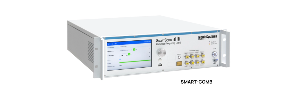
Now, you can buy a ready-to-go OFC as a single box, such as the one seen in Figure 3. The Thorlabs Compact Optical Frequency Comb is a compact, fully-automated optical frequency comb housed in a standard 19″ 3U rack housing, designed and built for use both inside and outside of the optics lab. It measures optical frequencies anywhere in the 630 – 2000 nm wavelength range, and can measure the frequency of external lasers with 14 digits of precision.
Q: What are the next steps in system and hardware evolution?
A: There is a considerable amount of ongoing work focused on the development of chip-scale systems based on microresonators, along with semiconductor processes and fabricating, but for optical signals rather than electronic ones. The compact size of these systems shows the possibilities of chip-scale and photonically integrated OFC sources. Advanced university-based photonic research programs are working on this with impressive success, as are independent research companies.
Q: All this OFC progress is impressive with respect to metrology, but what does it have to do with microwave oscillators?
A: Part 2 will explain this relationship.
References
[1] 20 years of developments in optical frequency comb technology and applications, Communications Physics/Nature[2] Frequency comb, Wikipedia
[3] Frequency Combs, RP Photonics AG
[4] Fundamentals of frequency combs: What they are and how they work, NIST
[5] Optical Frequency Combs, NIST
[6] Optical and microwave metrology, NIST
[7] Ultrastable Photonic Microwave Oscillators: Purity Verified, Microwave Journal
[8] Photonic chip-based low-noise microwave oscillator, Nature/Springer
[9] Compact and ultrastable photonic microwave oscillator, Optics Letters
[10] Photonic Microwave Sources Divide Noise and Shift Paradigms, Photonics Spectra
[11] A chip-integrated comb-based microwave oscillator, via Arvix
[12] Compact and ultrastable photonic microwave oscillator, ResearchGate
[13] Photonic Microwave Sources Divide Noise and Shift Paradigms, Photonics Spectra
[14] Optical Frequency Combs for Low Phase Noise Microwave Generation, URSI
[15] Integrated optical frequency division for microwave and mmWave generation, Nature
[16] Reaching Unprecedented Sensitivity in Cross-Spectrum Phase Noise Characterization, Menlo Systems
[17] Ultrastable Photonic Microwave Oscillators: Purity Verified, Menlo Systems
Related EEWorld Online content
Review: Tekbox TBCG4 harmonic comb generator
Review: Picotest J2150B comb injector
Lasers, optics, electronics and more yield terahertz sources, Part 3 – Infrared lasers and plasma
Understanding electro-optic modulation