
There are many applications where the designer needs to take an RF signal and divide it into two equal-power signals. This may be for a situation where one of the signals is to be used as a reference while the other is processed or modified and then compared to the unmodified reference signal.
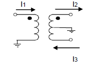
A power splitter is easy to build using a transformer with a center-tapped secondary side, seen in Figure 1. The outputs of the transformer have equal magnitude and opposite phase; the phase reversal is often not a concern, and if it is, it can be easily changed with an inverting amplifier. The quality of the splitter is a function of how close to ideal the tapped transformer is, and it can be quite good.
Two signal splitters and a diode bridge can be used to create a double-balanced mixer (DBM), a classic analog circuit for amplitude modulation (AM) and demodulation (here, “balanced” means that the normally grounded port of the device is instead floating).
Note that while over-the-air AM broadcast radio may be a declining form of communication, the AM process itself is still widely used in signal transfer and processing circuits.
The function of the DBM is to provide frequency down-conversion or up-conversion involving three critical signals in the signal chain: the intermediate frequency (IF), the local oscillator(LO), and the RF signals, with a structure shown in Figure 2.
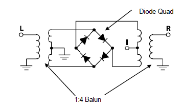
In down-conversion of a receiver, signals are sent to the mixer’s LO and RF ports to produce an output at the IF port. The tap of the LO transformer is grounded, and the center tap of the RF balun is used for extracting IF. For up-conversion at a transmitter, the down-conversion port conditions are rearranged, with signals going to the mixer’s LO and IF ports to produce an output at the RF port.
The double balanced mixer topology has four diodes in a ring or star configuration along with two baluns (one each for the RF and LO signal ports) and provides rejection of both the LO and RF content at the IF output. In its basic form, it uses a pair of 1:4 baluns/transformers and a quad-diode arrangement.
Key to performance quality is not only how close to ideal the baluns are, but how closely matched the diodes are. While early DBMs used individual discrete diodes (and earlier ones used vacuum tube diodes!), modern versions use diodes on a single substrate so their parameters are matched, and their unavoidable drifts track each other and so cancel out.
Making sense of it all
We have looked at only a few of the many transformer-based RF circuits. Implementation of the physical transformer takes one of three forms:
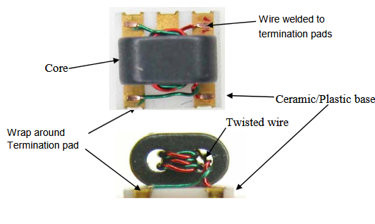
- Conventional transformers: the ones that most engineers think of when they hear “transformer” – are made with wire wrapped around a core, and are limited to an upper frequency of 2 GHz (that is an impressive upper range when you consider the reality of discrete-component RF circuits and parasitics).
- Transmission: line-type transformers using core-and-wire construction can operate to about 3 GHz, and to 5 GHz or higher using low-temperature cofired ceramic (LTCC) construction, as seen in Figure 3. They do not offer DC isolation from primary to secondary, so external blocking capacitors are needed to provide isolation (which is often not needed in these applications).
- Finally, less-known Marchand transformers (named after their inventor Nathan Marchand of Federal Radio and Telephone Laboratories, who published the design in 1944) operate to 6 GHz and higher and are now constructed using LTCC technology: they offer DC isolation from primary to secondary sides. The objective of Marchand’s design was to transform the RF-signal medium from coaxial to a two-conductor transmission line using an elegant and sophisticated arrangement of coaxial cable, a balanced line, and an RF stub.
Summary
Which technology is the right fit for a given application and frequency can be confusing. The choice is determined by the application itself, of course, along with the critical parameters such as frequency, maximum impedance ratio needed, acceptable maximum insertion loss, need for DC isolation, and power-handling capability.
To simplify the initiation of the decision process, the industry has separated transformer configurations into different groups and matched these groups to the applications. Reference 1 has a table which is an excellent summary of the situation and a guide to working through the process. In general, vendors of these RF transformers offer a significant amount of useful collateral that goes far beyond the basics of turns ratios, in order to help designers with a topic that is likely somewhat unfamiliar.
References
[1] AN-20-002 Application Note on Transformers, Mini-Circuits
[2] A Quick Guide to Mixer Topologies, Mini-Circuits
[3] Turn Ratio of a Transformer: A Complete Guide to Voltage, Current, and Coil Calculations, Allelco
[4] Marchand balun, Microwaves101
[5] The Marchand Balun: Past and Ever Present, Scribd
Related EEWorld Online content
Transformer applications go RF, beyond voltage step-up/down: part 1
Transformer applications go RF, beyond voltage step-up/down: part 2
The basics of AC-line isolation for safety, Part 1: The challenge
The basics of AC-line isolation for safety, Part 2: The solution
Long-wire dipole antennas: still viable after more than a century
RF transformer fabrication – Making the best of a non-ideal situation
FAQ on cable impedance: 50 Ω versus 75 Ω
VSWR and impedance, Part 5: Making a match