
An S-parameter matrix represents the ratios of a network’s incident and emitted waveforms.
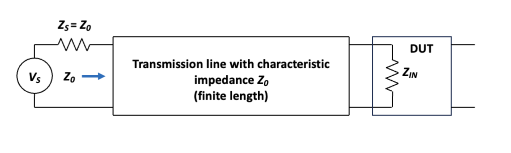
We concluded part 2 of this series with a look at surge impedance, and we began considering what happens when we launch a signal into a transmission line. Figure 1 shows the basic setup, where we have a transmission line of characteristic impedance Z0 applying a signal to a device under test (DUT) with an input impedance ZIN.
Q: What are the possibilities when we apply the signal?
A: If the DUT is a single-port device such as an antenna or dummy load, it can absorb the signal or reflect some or all of it back to the source. If the DUT is a multiport device, it can pass all or some of the signal on to downstream devices and reflect the remainder back to the source.
Q: Where do S-parameters come in?
A: Let’s take a closer look at our DUT from the figure. As shown in Figure 2, the DUT is a two-port device with incident voltage waves a1 and a2 applied to ports 1 and 2, respectively, while b1 and b2 represent waves reflected from or transmitted through ports 1 and 2, respectively.
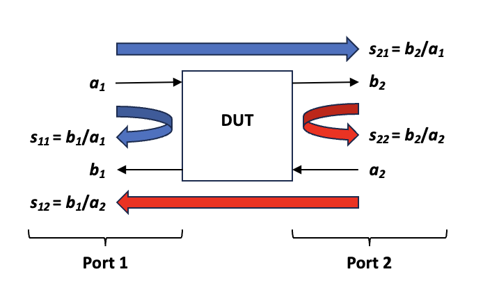
The S-parameters, then, are simply the ratios of incident and emitted waves, as shown by the equations in Figure 2. They are usually expressed in matrix form, where an n by n matrix represents an n-port network. For our two-port network, the matrix is
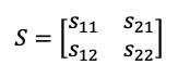
For the two-port case, s11 is also called the input reflection coefficient; s21, the forward transmission coefficient; s12, the reverse transmission coefficient; and s22, the reverse reflection coefficient. S-parameters are complex numbers having both magnitude and phase components, with the magnitude typically expressed in decibels.
Q: What causes the matrix format to be more suitable for the RF/microwave domain compared with low-frequency circuits?
A: Nothing. Recall in a recent series, we used a matrix format so we could use an online solver to solve Kirchhoff loop and node equations. In fact, we can characterize any circuit at any frequency using matrices, with low-frequency circuits lending themselves to Z-parameter analysis, where the letter Z (for impedance) takes the place of each letter S in the above matrix. For a two-port network, Z-parameters take this form:
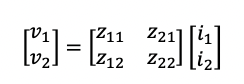
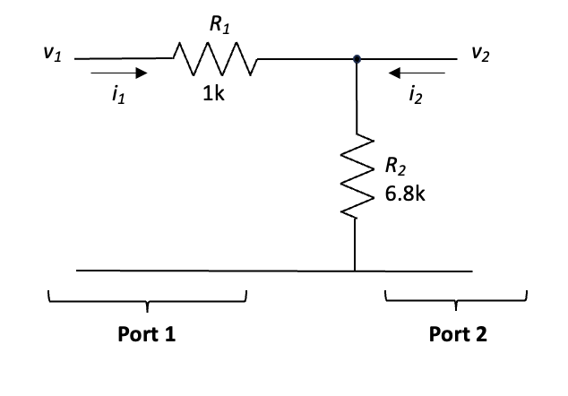
Consider the simple circuit in Figure 3. For this circuit, z11 equals v1 divided by i1 with port 2 open-circuited, or 7.8 kW, and z22 equals v2 divided by i2 with port 1 open-circuited, or 6.8 kW. z12 equals v1 divided by i2 for i1 equals 0, and z21 equals v2 divided by i1 for i2 equals 0, with z12 and z21 both also equaling 6.8 kW.
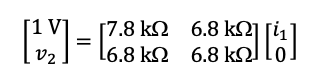
We can use these values to construct a Z-parameter matrix equation and solve problems such as, what is v2 if v1 equals 1 V and i2 is zero?
We can solve this equation as follows:
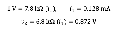
So this is a pretty complicated way of solving a simple voltage-divider problem, but it demonstrates that the matrix approach isn’t limited to RF/microwaves. In fact, if you have an S-parameter matrix, you can convert it to a Z-parameter matrix, and vice versa. Twenty-five years ago, I wrote an article[1] providing more details on the relationship between S-parameters and Z-parameters. In general, we use Z-parameters for low-frequency circuits, because it’s relatively easy to apply voltages to or insert currents into low-frequency circuit nodes and measure the responses. But when signal wavelengths shrink to the dimensions of our circuit, it becomes easier to apply a waveform and measure the resulting reflected and transmitted signals, and we use matched impedances instead of the open circuits we use for constructing Z-parameter descriptions.
Q: How exactly do we measure S-parameters—that is, what equipment do we need?
A: The vector network analyzer is the instrument of choice. We’ll conclude this series next time with a look at the details of making measurements.
Reference
What are S-parameters, anyway? EDN
Related EEWorld Online content
Making sense of test circuits with Kirchhoff’s laws: part 3
Measuring signals on transmission lines
What are insertion loss and return loss, and how can I measure them?
Should I use a spectrum, signal, or vector network analyzer? part 1
The principle of impedance matching
Understanding the basics: What is characteristic impedance?