
A 132-kW NVIDIA GB300 NVL72 configuration uses power shelves to feed compute trays through a 50 V DC busbar. At 12 V, the same load would draw approximately 11 kA. Raising the bus voltage lowers current at fixed power, while conductor loss falls with the square of current at fixed resistance. This article explains how 48 V rack power distribution shifts the bottleneck from the rack busbar into the trays. It also discusses why the bus stops near 48 V and how that ceiling limits further scaling.
Where rack current goes
Bus current follows I = P/V, while conductor loss follows Ploss = I²R. Quadrupling the bus voltage cuts current to one-quarter and resistive loss to one-sixteenth, provided conductor resistance remains unchanged.
In real-world deployments, rack designers spend much of that margin on thinner busbars and reclaimed rack volume rather than banking all of it as an efficiency gain. Figure 1 summarizes the thermal and fault-current constraints that determine the minimum busbar cross-section.
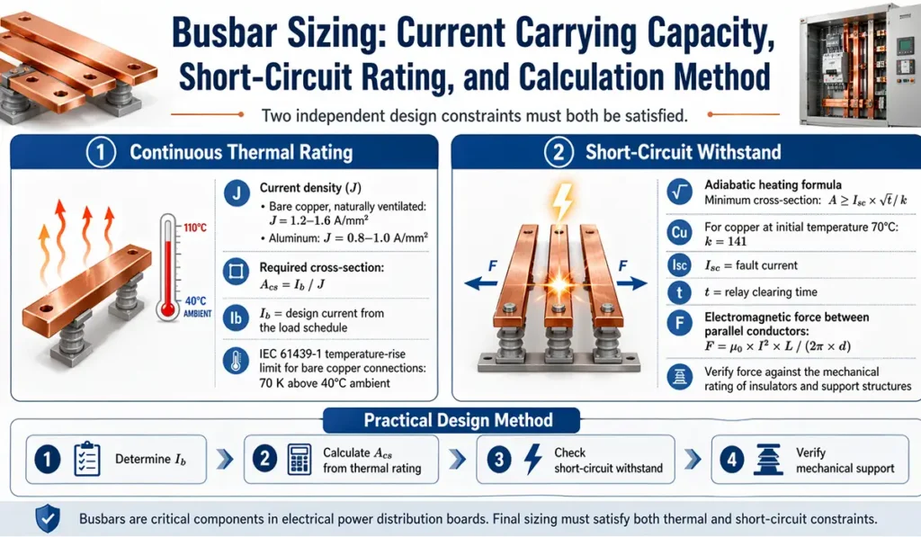
The theoretical 16:1 loss ratio represents the design headroom available with an unchanged conductor. Table 1 quantifies this relationship at a fixed 100 kW.
| Distribution voltage | Current at 100 kW | Relative I²R loss, same resistance |
| 12 V | 8,333 A | 1× |
| 48 V | 2,083 A | 0.063× |
| 800 V | 125 A | 0.00023× |
Table 1. Bus current and relative conductor loss at a fixed 100 kW. The 800 V row represents facility-to-rack transport rather than an in-rack bus.
In the GB300 NVL72, busbar current varies along its length because each tray taps the rail while power shelves feed it from the top and bottom. Segments nearest the feed points carry the largest aggregate current, which falls as successive trays draw from the bar. The resulting I²R loss is highest near those feeds, while contact resistance creates localized heating at blind-mate contacts. Both areas require focused qualification.
Why the bus stops near 48 V
Why stop near 48 V instead of raising the rack bus to 200 V and lowering current further? Safety classification rather than converter capability sets the boundary: IEC 62368-1 defines the ES1 voltage limit for DC sources as 60 V.
A bus that remains below this threshold avoids a safety-driven isolation requirement within the secondary power path. It also supports live-bus hot swapping without requiring higher-voltage service procedures. Because the high available fault current still poses a fire hazard, strict spacing and fault protection remain necessary. Crossing 60 V changes the electrical-energy classification and adds insulation and service requirements.
The 48 V class covers several nominal voltages below this ceiling. The 48 V option in Open Rack v2 specifies 54.5 V nominal within a 40 to 59.5 V operating range, while Open Rack v3 defines 51 V and 54 V tray-input options with narrower ranges.
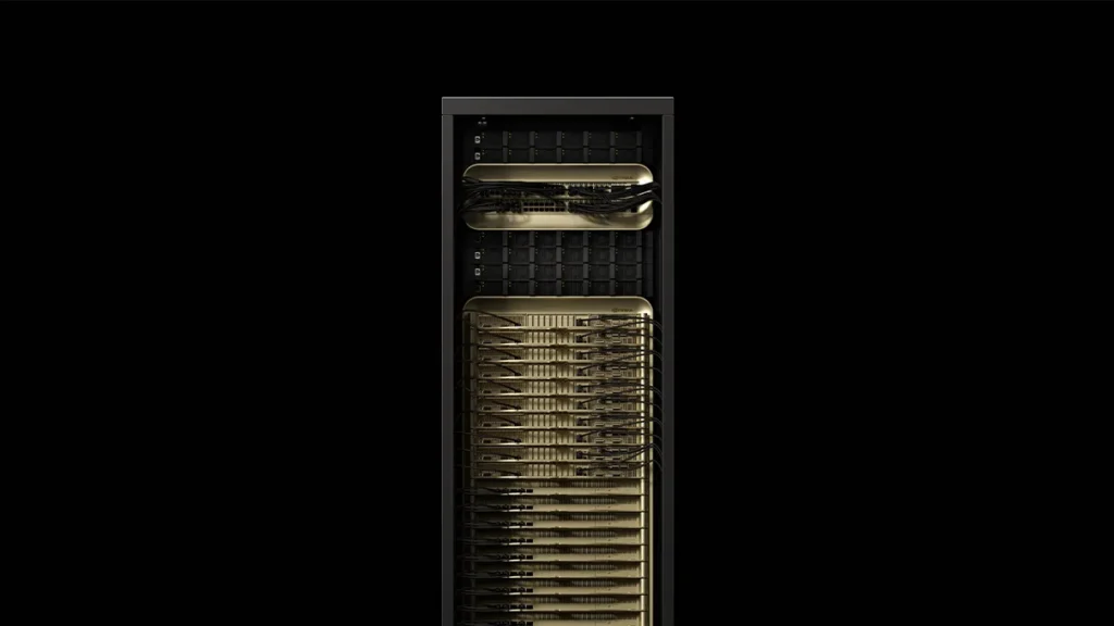
The GB300 NVL72 shown in Figure 2 uses 50 V nominal, with trays accepting 47.5 to 51.5 V. Although each design uses a different operating point below the same 60 V boundary, the 48 V designation remains.
What moves into the tray
Raising the rack bus voltage leaves current demand at the processor die unchanged. For example, a kilowatt-class AI processor operating at a core voltage below 1 V can draw more than 1,000 A at peak, with abrupt current changes during workload transitions.
The 48 V bus carries less current along the rack-scale path, yet the final converter must still supply the die at low voltage and high current. Transient performance along this final segment depends on loop inductance and package decoupling. On accelerator boards, designers now focus much of their power-delivery effort on this short path.
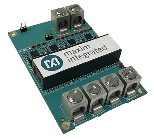
Earlier server boards typically split conversion into two stages. An intermediate bus converter dropped 48 V to roughly 12 V, and point-of-load converters beside the processor package then stepped 12 V down to core voltage. Figure 3 shows a compact 48 V-to-12 V converter that supplies a regulated 12 V rail for server peripherals.
High-current AI accelerator boards compress this chain. Vertical power delivery locates the final stage beneath the processor and sends current upward through vias rather than laterally across the board. This configuration shortens the high-current path from centimeters to millimeters.
Conversion loss follows the converters inward. A 10-kW tray draws approximately 208 A at 48 V. At 99% efficiency, a conversion stage handling that load still dissipates about 100 W inside the tray. Across a 132-kW rack, each percentage point of conversion loss represents roughly 1.3 kW.
Multiple stages can push aggregate loss into several kilowatts and concentrate it near the load. Cooling must then extend beyond the accelerators. Power modules and inductors may need dedicated cold plates, and at extreme density, even the busbar may require liquid cooling.
Where 48 V ends
The 132-kW GB300 NVL72 draws about 2.6 kA from its 50 V bus. Because the ES1 classification limits the bus to 60 V, current must rise with rack power. At 1 MW, a 54 V rack bus would carry roughly 18.5 kA. NVIDIA estimates that such a busbar could require up to 200 kg of copper. At that point, copper mass and rack volume would set the practical limit.
The industry’s response is to extend 800 VDC distribution to the rack. NVIDIA is working with Google, Microsoft, and the Open Compute Project to develop this architecture. Initial deployments convert AC to 800 VDC in a sidecar power rack within the row; subsequent designs centralize conversion at the row level and eventually at the facility level. Regardless of where AC-to-DC conversion occurs, rack-level converters step 800 VDC down near the compute load. At 800 V, the same 1-MW rack would draw 1,250 A, about 93% less current than at 54 V.
Summary
At 132 kW, a 50 V bus keeps rack current manageable without exceeding the ES1 voltage limit. At megawatt scale, copper mass forces the high-voltage boundary into the rack and drives the shift to 800 VDC distribution. Because the converters closest to the processors still operate from a rail below 60 V, the ES1 ceiling will outlast the 48 V rack bus.
References
Reimagining Power for AI: Shaping the Future of AI Acceleration: Part 3 of 3, Analog.com
Liquid-Cooled Busbars, Molex
AI and High-Performance Computing,Empower Semiconductors
NVIDIA GB300 NVL72: What One Rack Delivers, and What It Demands, ModuleEdge
Lenovo NVIDIA GB300 NVL72 Rack Scale AI, Lenovo
How New GB300 NVL72 Features Provide Steady Power for AI, NVIDIA
NVIDIA 800 VDC Architecture Will Power the Next Generation of AI Factories, NVIDIA
NVIDIA 800 VDC Architecture, NVIDIA
Why Scaling AI Compute Performance Requires a New Power Architecture, NVIDIA
AI Data Center Power: 48V, Busbars & VRM Architecture Guide, WhyChips
Why 48 V Still Matters in AI Data-Center Systems, Flex
Related EEWorld Online content
Breaking the 12-V Bottleneck: the Shift to 48-V Power
AI Data Center Power Distribution: Part 1
AI Data Center Power Distribution: Part 2
AI Data Center Power Distribution: Part 3
Soft-Termination MLCC Reduces ESR in 48 V Systems