A special kind of HiL testing accelerates the development of advanced driver-assistance systems.
Bernhard Holzinger, Automotive and Energy Solutions • Keysight Technologies
Industry watchers are still optimistic about the adoption of connected autonomous vehicles (CAVs). But CAVs will only become reality if consumers, regulators and the insurance industry all have an unshakable confidence in the technology. The process of building confidence in advanced driver-assistance systems (ADAS) will entail hundreds of millions of miles of road testing—actual or simulated—to fully explore corner cases and thoroughly validate new designs.
ADAS make decisions through use of sensors that perceive the environment of a car and the current driving situation. Today, software-based simulation systems are used to develop and test ADAS functions. However, traditional integration and system-level tests cannot ensure ADAS will operate properly in the real world. Further, these tests take place late in the development process. So design changes necessitated by ADAS tests become costly, time-consuming, and delay the start of production (SOP).

The strategy to avoid SOP delays starts with higher-level scenario testing performed earlier in the development process. Detailed emulation of real-world conditions enables thorough debugging and troubleshooting of complete subsystems long before vehicles take to the road.
The goal of ADAS is to not only assist the driver, but eventually enable fully automated or autonomous driving. The American Automobile Association (AAA) tested the performance of available ADAS for five different brands of cars. The test results were rather disillusioning if one considers the main takeaways:
For controlled closed-course evaluations, each test vehicle’s ADAS generally performed to the owner’s manual specifications. But during a roughly 4,000-mile test drive on public roads consisting mainly of freeways, 521 events were noted, translating to approximately one event every eight miles. Most notably, 73% of the events related to lane-keeping functions.
Challenges in ADAS validation
In summary, AAA concluded ADAS interfered more than it assisted. This rather harsh verdict glosses over test results that show ADAS worked as expected in the controlled environment. However, the AAA test drive also illuminates the difficulty in testing ADAS for all the driving scenarios one might encounter on public roads. The results point to a couple of key challenges for ADAS developers: First, it is difficult to create sufficiently high test-coverage that fully addresses the seemingly uncountable number of potential real-world scenarios. Second, the deployment of fully autonomous operation in the future will require significantly more on-board sensors. Consequently, the verification of fully autonomous systems will require increasingly complicated test setups.
To address these challenges, it’s worth taking a closer look at the automotive development cycle with an emphasis on verification. Automotive development is often conducted according to a scheme specified in the ISO 26262 framework. Called the V-model, it depicts a development cycle focused on ensuring functional safety.
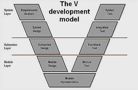
The V model starts with the overall system definition and then moves down through system and component-level design of both hardware and software. The bottom of the V is characterized by the construction of prototypes and the final implementation. The right-hand leg of the V covers verification, moving upward through the testing of individual components, the resulting subsystems, and then the complete system.
As engineers progress from module tests towards system validation, they may start with pure simulations, especially when the testing of software is involved. However, the software must interact with the real hardware when progressing up the V-model to submodules and eventually to the complete system, thus increasing the complexity and costs.
One way to counteract these potential costs is to find design flaws earlier in the verification cycle, as exemplified by the V-model. This practice helps simplify verification tests, and it also helps prevent failures that can be costly to remedy if found later on.
Even so, validation of the complete system requires road testing of a fully integrated vehicle. This approach has two noteworthy shortcomings: First it is expensive and, second, the results obtained from random, real-world environmental conditions are not easily reproducible. Reproducibility becomes important if the system-under-test is producing intermittently erroneous behavior.
Consider an adaptive cruise control system as an example. Based on inputs from a radar sensor, the system should control braking and acceleration to produce the desired cruising speed or maintain a safe distance from a vehicle directly ahead. Verification of the control algorithm starts with a simulation system that replicates the road environment, the radar sensor, and the physical behavior of the car. The simulation can verify the behavior of the algorithm in different scenarios. This type of test setup is referred to as software in the loop (SiL).
Over time, hardware elements can be added to the system. For instance, a test setup could include an electronic control unit (ECU) that will later be integrated with the vehicle and, for example, a radar sensor. This type of test setup is referred to as hardware in the loop (HiL).
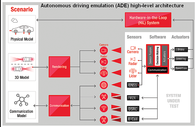
Specialized test equipment can now address such scenarios. One example is the Keysight HiL-based system called the autonomous drive emulation (ADE) platform. It supports the testing of ADAS at the component and system levels.
The test scenario is set up using a simulated environment, which implements a real-world situation all around the vehicle. This simulation is used to extract the required information to stimulate sensors such as cameras or radar units, and link to available communication channels, such as vehicle-to-everything (V2X).
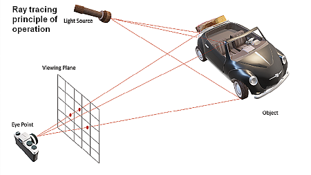
To extract the required information for sensors, such as radar or cameras during the test, ray-tracing technology can be used. We all have seen this in modern computer games. The goal is to determine how an object must be displayed on a viewing plane (i.e. the monitor in case of computer games) to recreate its appearance from a certain view point as it would be observed in the real world. For a computer game, the relevant view point is the player in front of the monitor. When testing an ADAS system, it’s the location of the camera, radar, or any other kind of sensor.
In a ray tracing simulation, the object is represented by a wireframe model in which the object surface is split into small triangular tiles, each having a flat surface. Sticking to the example of a computer game: For every pixel in the viewing plane (i.e. the monitor), the algorithm can draw a straight line (i.e. trace a ray) from a specified viewpoint (i.e. the anticipated position of the player in front of the monitor through the pixel to the object. This ray will strike one tile of the wireframe of the object. Additionally, for an object to be seen, it must be illuminated. Consequently, another ray is traced from this tile to the light source. From the angles at which these rays hit the tile and from its material properties (e.g. its color), analysis can determine how this pixel must be displayed (e.g. color and brightness).
This same algorithm can also be used for radar. The light source is the radar transmitter. The relevant material properties would be included, and spatial velocity would be factored in to calculate Doppler effects. Even so, the same principles apply.
Handling inherent processing delays
Modern graphics processing units (GPUs) provide hardware acceleration for ray tracing algorithms. Thus, they are great tools for providing the computing power this approach requires. However, there will always be a processing delay even for the fastest GPUs, which can become an issue.
For example, assume it takes the ray-tracing algorithm 100 msec to deliver its data to a radar target simulator. This is the time needed for the algorithm to take a snapshot of the scene, perform its calculation, and present data to the radar.
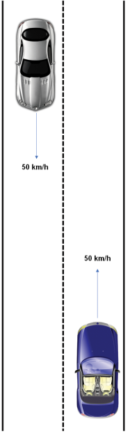
Now consider a typical urban traffic situation: Two cars approach each other and both are traveling at 50 km/h. That’s a relative velocity of about 28 m/sec, and within the 100-msec interval they have reduced the distance by 2.8 m.
This is an easy scenario for an open-loop system to handle. It can be compared to watching a movie–it doesn’t matter if viewers perceive the data only after its recording. If other sensors are involved, then all are stimulated consistently. In other words, the processing delay must be the same for all the sensors to realize overall measurement synchronism.
When the ADAS reaction is incorporated in the test, the closed-loop approach is necessary. Here, the simulation includes the vehicle reaction. For instance, if the ADAS decides to hit the brakes in an emergency, the vehicle slows. There is then an impact on the data sent to the radar.
The loop is closed using an HiL system that also emulates other components within the car that do not relate directly to the ADAS. The latency issue is overcome via what’s called a nowcasting algorithm. For context, consider that weather forecasts use current data to predict what will happen in the future. In contrast, nowcasting employs outdated information – in this case data that is 100 msec old – to predict the current situation.
This approach enables the simultaneous testing of an ECU, its software, and the real sensors. As explained above, the technique requires the simulation of several sensors and communication channels, not only in a synchronized way, but also with an algorithm (nowcasting) that compensates for the processing delay .
With these requirements met, the ADE platform allows the testing of an ADAS from the component level on up to the sub-system level, long before a vehicle is tested on the road. The goal is to reduce the overall cost of testing while improving test coverage during early stage verification. Ultimately, this approach helps improve the performance of ADAS when deployed on public roadways.