Microelectromechanical systems (MEMS) have come a long way from 1986 when the Defense Research Projects Agency (DARPA) first coined the term, with a global market for MEMS devices of more than $12 billion. Nearly all of those devices are sensors, although the market for RF switches and other high-frequency MEMS devices is starting to increase. While traditional MEMS devices have been categorized primarily as low-power devices, MEMS technology can also be used for high-power (multiple kilowatts and beyond) applications, even though the prevailing opinion has been that they’re too small, fragile and unreliable for handling all but the lowest voltage and current loads. By using the proper materials, MEMS switches can handle much more of both, and their benefits when compared to traditional electromechanical relays (EMRs) and solid-state relays (SSRs) are significant.
While wide-bandgap (WBG) semiconductors have been the primary focus for reducing the size, weight, and thermal footprint for advanced power conversion applications, it’s important to remember that the relay is still the “go-to” device for industrial controls and protection. In these applications, power relays, contactors, and breakers distribute and manage the flow of AC/DC power to all the loads, from lights to motors to robots and all the appliances and devices most people use every day. The promise of a MEMS power relay is to bring the miniaturization, power efficiency, and thermal improvements to industrial controls, just like WBG devices are bringing to power conversion.
A MEMS switch (Figure 1) functions much like an EMR, except that a MEMS switch is smaller than a human hair, is created on a wafer in a semiconductor fab, and weighs almost nothing. An entire array of hundreds of MEMS switches will still be a fraction of the size of a single EMR or SSR. MEMS switches also consume practically no power, have fast turn-on/turn-off speeds, and have been demonstrated to function for billions of operations.
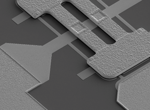
In the case of electrostatic MEMS switches, when no voltage is applied to the switch’s gate electrode the actuator remains at rest, in an open state. When a sufficient DC voltage is applied to the gate electrode, the generated electrostatic force causes the actuator to bend downward, meeting the contact below. This connects the input to the output so that current can flow. All this occurs in microseconds.
MEMS switches haven’t been considered for power-switching because their miniature structures have not been able to withstand high temperatures generated when large currents are flowing. Also, the voltage across the open terminals of such a device can create arcing that can damage the device if not managed properly. This has precluded their use in high-voltage and high-current applications for which they are in all other respects ideally suited. As a result, development has focused on low-power (<5 W) RF MEMS switches.
Getting to High Power
There are three main requirements for MEMS to be considered for high-power switching. First and foremost are manufacturing the devices with materials that are not only low-loss but able to withstand high-temperatures. Second, protection must be provided for the MEMS switch so that it can withstand the high voltages and currents encountered during switching transitions. Finally, to be commercially viable, they must be made in a fabrication process that is proven to be reliable and able to consistently produce devices that can survive for decades of useful life under relatively harsh environmental conditions.
Needless to say, this is not trivial, and throughout the past few decades of MEMS development, technologists have focused instead on sensors that do not need to handle high-voltage and high-current loads. Satisfying such requirements is more difficult for several reasons, not the least of which is the microscale size of their functional elements that like the billions of transistors in a microprocessor require a microscope to see. There have nevertheless been consistent efforts over the years to develop MEMS switches that could perform reliably in industrial applications, where they would need to survive massive number of switching operations over many years of use.
General Electric began focusing on high-power MEMS switching in 2004, with the goal of creating faster circuit breakers and protection devices. Many of the company’s products need to operate under extreme environmental conditions, including gas turbines, jet engines, trains, wind turbines, and magnetic resonance imaging (MRI) equipment. Developing and manufacturing MEMS switching solutions required expertise across a wide range of disciplines, from high-reliability modeling to semiconductor processes and packaging, and most critically, high-temperature alloys.
GE’s vision 15 years ago was an alternative to large, slow EMRs that could handle high power with the speed, size, and reliability of solid-state technology, but without the associated losses of a semiconductor. Their research concentrated on MEMS switch technology, but in 2004 MEMS was embryonic, with poor reliability and very little development for applications for harsh industrial requirements.
However, if these challenges could be overcome, the advantages would be enormous, so they took on the challenge. A key area of focus was on the materials used for building micro-scale MEMS switches. Although pure metals are excellent conductors, when used as a mechanical actuator they can deform with time and temperature, limiting their life. After an exhaustive process of materials evaluation, the GE researchers created a fabrication process for building MEMS switches with a high-temperature-resistant metal alloy that dramatically reduced deformation.
The resulting actuators had mechanical properties near those of silicon, with the conductivity of a metal and the ability to scale up to hundreds of amperes of current and kilovolts of AC/DC voltage. Along the way, to remedy the problem of arcing during switching transitions, the researchers developed a hybrid design consisting of a MEMS switch combined with a traditional MOSFET for protection.
As shown in Figure 2, the basic structure of the hybrid switch is quite simple. The benefit derived from the MOSFET is its ability to handle a high voltage/current overlap during the switching transition.
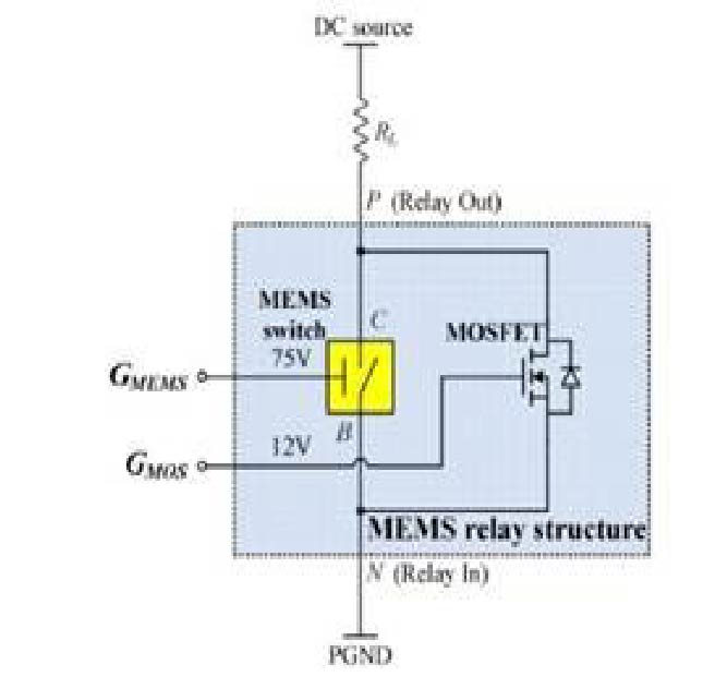
In this circuit, the MOSFET is turned on before the MEMS switch makes its on-to-off transition, which results in almost zero voltage across the MEMS switch terminals. As the MEMS switch requires isolation between control and power circuits, a transformer is used to supply it. The transformer-isolated 5 V power supply provides on-off control voltage as well as the gate voltage to drive both the MEMS switch and MOSFET. The outputs of this isolated driver are high-voltage (75 V) for the MEMS switch and low-voltage (12 V) for the MOSFET. The control circuit in which they’re employed (Figure 3) performs a variety of other functions as well with just a few inexpensive devices.
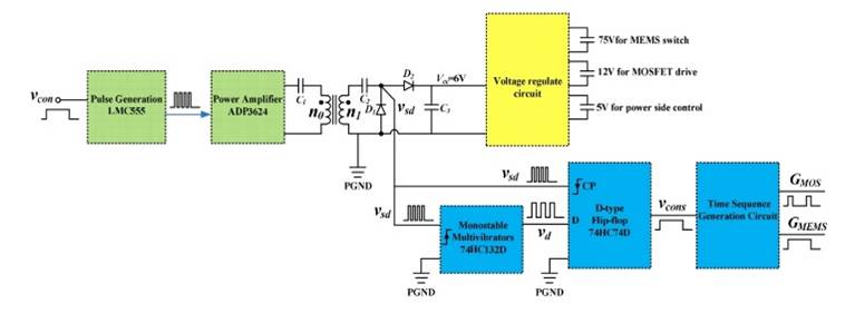
Referring to Figure 3, when the 5 V turn-on control signal (vcon) is applied on the primary side of the circuit, the LMC555 generates a 500 kHz pulsed waveform, which is amplified by the ADP3624 to become the driving voltage for the transformer, with C1 filtering the DC signal components. The voltage-doubling rectifier circuit steps up the transformer secondary voltage to 6 V (Vcc) that acts as the input to the voltage regulation circuit. A step-up DC-to-DC device generates the 75 V for the MEMS switch’s gate terminal, and a voltage doubler generates 12 V for the MOSFET gate. The linear voltage regulator provides 5 V power for the control circuit.
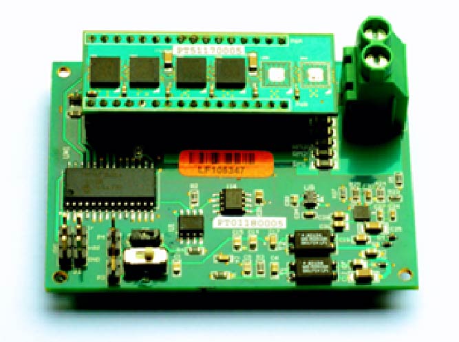
The secondary side provides the MEMS switch on-off signal (Vsd) to the control circuit, and the MEMS-switch on/off signal (Vcons) in the secondary side is generated by the D-type flip-flop. Vsd is the flip-flop’s falling-edge trigger and the input (Vd) of the flip-flop is derived from the output of the multi-vibrator. A complete power relay demonstration board is shown in Figure 4.
Evaluating Performance
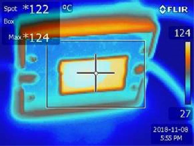
Figure 5 shows a comparison of the MEMS power relay and a traditional SSR when tested under load to show the benefits of using massive arrays of MEMS switches to reduce resistive losses, and thus generate less heat when large currents are present. In this example, the MEMS power relay was tested with 16 A steady-state load and a measured Ron = 15 mΩ. No heat sink is added to the MEMS switches. The SSR was tested with de-rated 12.5 A load and a measured Ron = 50 mΩ. It is observed that even without a heat sink, the highest temperature of MEMS switch is 92°C at 16 A load current. While with conventional SSR relay, the highest temperature is 124°C with its self-contained heat sink at lower current of 12.5 A. Reducing heat can eliminate large heat sinks and reduce the overall footprint and volume required for relays in many applications.
.png)
A Promising Future
While MEMS technologies have taken a long time to develop, the number of applications for which they are being used continues to grow every year. One of the most promising is switching high levels of AC and DC voltage and current, potentially replacing EMRs and SSRs in applications for which MEMS technology has never been used. This has become possible only recently, resulting from the availability of high-temperature-resistant metal alloys that dramatically increase reliability and a suitable high-power-capable MEMS switch fabrication process, along with combining these MEMS switches with a MOSFET protection circuit.
Realization of these capabilities could not have come at a more opportune time, as more and more systems are being powered by electricity rather than fossil fuels, and the design of almost every type of product is focused on reduced size, weight, power consumption, and cost. MEMS technology is a nearly-ideal solution for these applications, as it has been for so many others, because of the unique properties they bring to the table, different from both traditional mechanical and semiconductor devices. As a result, it’s sure that in the very near future, MEMS switches will become much more commonly used in high-power applications.
