Reliable and robust power conversion used to be the exclusive “must have” for mission-critical data centers, internet service providers, and communications industries. Today, however, system designers across a host of commercial and industrial markets are looking at many of these same ruggedized power solutions to solve their challenges—from dissipating heat and operating in harsh environments, to ensuring reliable power for “can’t-fail” applications.
The need for highly reliable and robust power for military and aerospace applications, for example, has been around for some time. Aerospace systems employ highly redundant power systems operating in compact packages that must withstand a range of temperature and atmospheric conditions. In the medical equipment industry, especially in patient-care products, reliable, safe, and robust power systems must provide life-critical support while also providing safe operation for both healthcare workers and patients.
Many industrial settings—both inside hot, gritty manufacturing facilities and in outdoor settings with extreme heat and weather conditions—require power supply units (PSU) to operate in extremely harsh settings. Hot, humid, and dirty air quality can affect system performance and the overall life cycle of the power supply. Power in outdoor settings such as broadcast, cellular or utility distribution equipment, for example, needs to operate reliably in all kinds of conditions, including extreme heat, rain, snow or even variations in atmospheric conditions.
As we look across these applications, electrical and power design engineers face several challenges: mitigating failure from mechanical cooling systems; dissipating heat, the natural byproduct of power conversion; and protecting PSUs from harsh indoor and outdoor environmental elements.
Mechanical Reliability
Ironically, with advances in digital controls and smart power conversion systems, many PSUs still rely on mechanical fans to direct airflow over the hot surfaces of a PSU to remove heat. Using fans for direct airflow cooling makes sense in many applications where component density isn’t an issue or when a device’s enclosure has enough room for adequate airflow.
However, adding a mechanical element, such as a fan, has a direct impact on overall reliability—a problem for rugged applications where access to systems for maintenance or installing replacement parts is an issue. Fans also contribute to lower mean time between failure performance, boosting both system failure rates and raising maintenance costs. In outdoor applications, dust accumulation and harsh operating conditions can considerably limit a fan’s reliability as well. Further, in some applications—such as hospital settings where medical equipment is in use—the noise generated by a constantly whirring fan motor is unacceptable for patients and staff.
Mitigating Heat
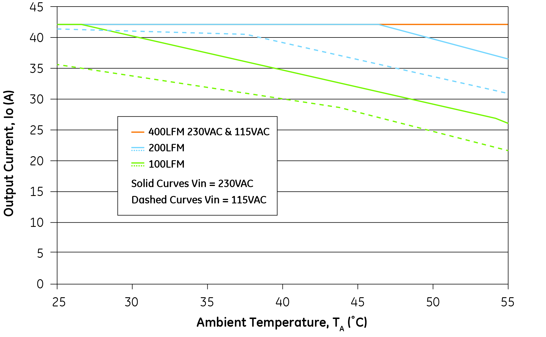
In harsh and rugged conditions, where using fans to reduce heat is either not practical or unreliable, designers look for alternative, fanless cooling techniques to dissipate heat away from the PSU and to improve potential power conversion capacity, performance, and component life cycle.
Figure one, for example, shows how the power output capacity is derated as ambient temperatures rise.
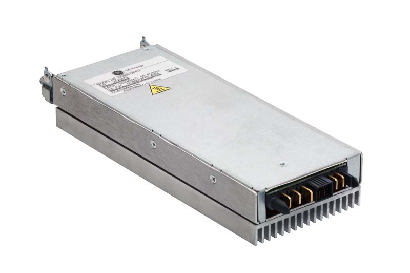
Designers can employ a range of conductive-cooling methods, such as heat sinks, heat pipes or cold plates, to conduct heat through cooler materials and away from the PSU or other electronic components. A heat sink consists of a metal attachment connected to the PSU or another component to conduct the heat away from its source (see Figure 2). Heat sinks, while simple, can take up valuable physical space that might be better used for other purposes while also adding weight to the power supply.
Using a heat pipe to conduct heat away involves the use of a pipe with a circulating liquid. One end of the pipe is in contact with the hot surface, which vaporizes the liquid. When the vaporized liquid encounters the cooler surface in the pipe, it condenses back into a liquid state and recirculates through the cooling system. Heat pipes can be effective in carrying heat away from the heat source to a heat transfer mechanism, yet designers need to cope with the additional space requirements and the potential for leaks damaging the electronics.
A third method, a cold plate, relies on a fluid—either water or some other refrigerant—to remove heat. Typically, the cold plate has small pipes in metal casings embedded beneath the surface of the plate. When the refrigerant moves through these pipes, it removes heat from the surface of the plate. Again, the extra space required for this method of cooling can be a consideration, along with compensating for potential water condensation.
An additional method of conductive cooling, called “potting,” involves filling the power supply enclosure with heat-transferring materials, such as epoxies, silicone elastomers, and urethane/polyurethane. This thermally conductive material carries heat to the top of the sealed enclosure where external airflow or other cooling mediums conduct the heat away.
While dissipating heat is a primary design challenge for engineers, extreme cold in outdoor settings also presents performance and reliability issues for power supplies. Extreme cold, though not as damaging as extreme heat, can also result in abnormal operation of the components, causing slow start up time, high ripple, instability, etc. In most cases, as a device starts up, the component temperature rises, bringing the operation within specification after a few minutes. In some cases, the device can be warmed by an external heating coil to ensure the components perform within specification at all times.
A conversation about air cooling also needs to include a discussion of elevation and atmosphere. Simply put, at higher elevations, the lower air pressure or density can result in less efficient convection cooling. For example, a 100 W power unit with an operating temperature rating of 50 C at sea level will have to be derated to less than 100 W power at 5,000 meters above sea level.
Ruggedized Modules for Board-Mounted Power
The equipment enclosure design and cooling techniques described above for PSUs can also greatly mitigate the challenges presented by temperature and mechanical stresses for board-mounted power. Additionally, for isolated and non-isolated DC-DC converters, designers can employ ruggedized versions of DC-DC converters that are available from many suppliers. These ruggedized versions are usually suitable for operating temperatures of up to 105 C and can withstand higher mechanical stresses than standard modules.
Harsh Environment Conditions
Environmental challenges—both outdoors and inside buildings—can also greatly degrade the performance, power rating, and longevity of power conversion modules. Outside, both water and humidity can erode performance and reliability, while inside manufacturing facilities, humidity, air-born particulates, and corrosive fumes create similar challenges. In addition to affecting performance and ratings, dirt, dust, and humidity can form arcing between high-voltage component leads, damaging components.
Traditionally, placing a cover over the system and power components mitigates some problems, but humidity, water, and dirt can still make their way onto the printed circuit board. A cover can work in limited indoor settings, but obviously is not a solution for outdoor applications.
To better protect against water and other contaminates, power designers can specify a conformal coating for the power component or for the entire board surface. Typically, a silicone or urethane coating covers the component, sealing it from water and humidity, dirt, and potentially corrosive fumes. This method can be a very cost-effective way to protect the components.
It does, however, have a drawback; conformal coatings restrict cooling airflow passing over the device, degrading either the power or temperature rating. For example, a 100 W power component rated for 65 C performs well within a performance specification operating at 50 C. With the air cooling limited by the coating, however, device temperatures can rise and result in a derated operating condition.
Excessive heat also can degrade the capacity of the power conversion device, such as an electrolytic capacitor, affecting its life cycle rating over time. For example, a device designed to operate at peak performance for 10 years might see the performance drop at 8 years if heat is not well dissipated.
Another extreme approach to protecting power conversion modules—whether used inside or outside—is to place the PSU in a sealed enclosure. While there are cost and performance trade-offs, the approach fully protects the device from air contaminants, humidity, water, and even a range of physical tampering—all defined as “Ingress Protection (IP).”
The definition of “harsh” can also apply to environments or processes where excess vibration can impact the performance, reliability or operating longevity of a PSU. For example, military vehicles, TV broadcast vans, and motor boats are subjected to shock and vibration that is transferred to the PSU mounted inside. To prevent failures under those conditions, PSUs in these settings generally use anti-vibration compounds, such as room temperature vulcanization, adhesive sealants or conformal coatings, to keep the components, screws, and boards in place.
Power designers face a number of issues, including thermal management, mechanical reliability, and harsh environmental conditions that all impact output capacity, performance, and longevity. An expanding set of PSUs offers a combination of tools and approaches to meet growing power conversion demands across industrial and commercial applications.
