 The D-Rex is billed as a ferocious yet loyal dinosaur robot with an independent personality. The toy combines robotics, interactive sensors and reptilian-like skin. He walks, follow the sound of your voice and makes funny noises. Weighing in at about 8.5 lbs, D-Rex stands a little less than two feet high.
You interact with D-Rex using a remote unit fashioned in the shape of a bone which is equipped with five buttons selecting various modes of operation. And the remote is a good place to start the teardown. Held together with ordinary Phillips screws, the bone contains a single PCB and
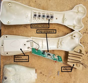
The bone remote showing its PCB, antenna, and buttons.
the antenna as well as nonrechargable batteries. The remote communicates with D-Rex using a 27 MHz signal. This is the same frequency as used for common RC toys. So it’s likely the D-Rex remote uses a repurposed RC transceiver chip to send commands to the dinosaur. We can’t tell for sure what the chip is because it uses chip-on-board packaging, basically just a blob of epoxy over the IC with no markings. This is the only IC on the remote -control PCB. Other components include a crystal for frequency stability and numerous discrete components.

The antenna and accelerometer/mic assembly.
The 27-MHz antenna on the bone remote is interesting in light of the fact that a quarter wavelength at 27 MHz is about 9 ft. Obviously, the D-Rex designers couldn’t give the remote a 9-ft. antenna, so they settled for an antenna consisting of a wire wrapped several times around a piece of cardboard that fits in one end of the bone. And it’s not clear whether there’s an antenna matching network on the PCB, so it’s likely the antenna isn’t exactly a superb radiator. That would explain some of the user reviews we’ve noticed griping about a short range between the remote and the toy.

D-Rex’s face beneath the skin.

The neck seam becomes visible when you cut away D-Rex’s collar.
The D-Rex has a skin made of rubbery material. The material is in sections that are bonded together at seams that are placed in unobtrusive places or which are hidden. For example, D-Rex’s collar seems to only service the purpose of hiding the seam between the head and body skin. The skin attachment points are along the mouth, feet, end of the tail, and the eyebrows so D-Rex can change his expression slightly by moving a small platform above each eye to which the skin glues.
Removing the skin reveals, among other things, the antenna D-Rex uses to receive 27-MHz signals from the bone-shaped remote. The antenna consists of wires bonded to two pieces of copper foil pasted on D-Rex’s head. The antenna is necessarily electrically short for 27 MHz, much shorter than a quarter-wavelength at that frequency, so the copper foil is evidently an attempt to boost the antenna’s signal reception. The receiver chip itself sits on a PCB residing in the dinosaur’s torso.
As on the PCB for the remote, the main ICs on the D-Rex boards all use chip-on-board packaging, so there’s no opportunity to look up part numbers to see what’s going on. But we can make a few educated guesses about functions based on the D-Rex architecture.
In the case of the remote-control functions, for example, the D-Rex designers may have been forced to improvise a bit because ordinary RC vehicles generally contain two motors at most that obey remote control commands. D-Rex, in contrast, contains five electric motors: one wiggles the tail, another powers the legs, a third sitting in the left foot assists in locomotion, a fourth turns the dinosaur’s head, and a fifth moves the eyes and mouth. All these motors play roles in actions initiated via the bone remote. It could be tricky to control them with a single RC receiver IC designed to handle two electric motors at most.

The front of the main PCB with what look like motor drivers called out. The backside (below) holds what may be the RF receiver and RF input amp.
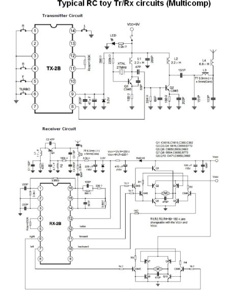
Typical RC transmit/receive circuits. Also note the reversible motor drives.
The main PCB, which resides in the dinosaur’s torso, holds the 27-MHz receiver IC. Circuit designers often separate RF circuits from the rest of the PCB functions, and that is the case with D-Rex. The main PCB contains a mezzanine board whose 32 connections are soldered directly to the main board. The mezzanine board contains two ICs in chip-on-board packaging which probably comprise the 27-MHz receiver. One would be the receiver itself. Judging by D-Rex’s short antenna, the other IC could likely be an RF front-end amp/filter necessitated by the weak signal reception.
It’s pretty clear that the reverse side of the main PCB holds the drivers for all of the five D-Rex motors – tail wagger, head rotator, main leg locomotion, left-leg motor, and facial movements. Each of these driver circuits are H bridges with catch diodes. The point of using an H-bridge driver rather than something simpler is that an H-bridge can drive the motor in either direction.
The D-Rex walking mechanics mainly consist of a gearbox, a tension spring on each leg, and an ankle joint on

D-Rex’s leg muscle moves because of this offset peg.

Visible with the torso and gearbox cover removed are the cams that push the COM to one side (larger cam) and move the leg (smaller one). Inside the left foot can be seen the motor/geartrain that is a bit mysterious to us.
each leg. D-Rex also contains a plastic “quadriceps” muscle on his leg. To simulate muscle movement while walking, the front of the quadriceps piece moves up and down a few degrees thanks to an offset follower powered from the main locomotion motor.
The D-Rex’s algorithm for walking resembles that of many other walking toys. The main idea is to move the robot’s center of mass to one side sufficiently to allow the opposite leg to swing forward and plant (or backward for backward walking). When the leg plants, the COM shifts to that side and the cycle repeats. This works so long as the COM projection onto the ground always stays within an area defined by the outer edges of D-Rex’s feet. (Readers may note that the dinosaur has relatively large feet for a toy this size. Easier walking stability is probably one reason why.)
D-Rex’s walking happens via a gearbox mounted in the torso with a drive shaft protruding from two sides, one for each leg. On each drive shaft sits concentric cams. The inner cam tilts the D-Rex torso to the opposite side while the foot is planted. Once the weight shift has happened, the outer cam pushes a linkage arm connected to the leg which lets the now free-swinging leg move forward. Then the foot makes contact with the ground.
The feet incorporate an ankle joint that facilitates the side-to-side movement of the COM. The ankle joint lets the foot pivot on its axis running heel-to-toes. This pivoting lets the weight-bearing leg angle out slightly as the COM shifts toward it, allowing the other leg to lift off the ground and be pushed forward by the driving cam. The ankle joint itself consists of a pinned support and a spring-loaded support that resembles a pushbutton switch, though it contains no electrical connections.

D-Rex has an ankle joint that lets the leg pivot as weight shifts from side to side during walking. Bottom, another look at the foot motor drive.
D-Rex’s left foot also contains a motor and gear drive assembly whose function was a bit mysterious, at least to us. The motor slightly rotates a plastic disk which mounts to the inner bottom surface of the foot. The disk sits under a small portion of the leg assembly but doesn’t seem to touch it. Also in the left foot is a sensor containing four tiny mechanical switches. The switch actuators don’t seem to touch anything. So we are flummoxed as to the purpose of the sensor as well.
Finally, the motor driving the legs seems to get position feedback from what is apparently a custom-made encoder-like wheel that sits on one of the drive shafts. All the encoders on D-Rex have a similar design. One side of the encoder consists of a single metal piece with prongs that extend up to touch the other side of the encoder. This piece rotates as the drive shaft spins. The other encoder piece is PCB material patterned with three different metallizations that is attached to the gearbox housing. The inner-most metallization is a continuous ring.
The patterns on the outer rings vary depending on the function of the motor. In the case of the locomotion motor, the next is a ring continuous except for two gaps

One of D-Rex’s encoder assemblies. As it turns, the metal piece connects the center conductor to the outer gapped traces.
180° apart. The outer-most ring consists of two groups of nine metal spots separated at one end by a metal area and by a gap 180° away. As the metal piece turns its prongs touch the continuous inner ring, the half-circle center ring, and the outer spots. The effect is to generate two signals as the drive shaft turns, one consisting of long pulses, the other short pulses. It’s not entirely clear to us what the D-Rex does with the long signals.
A few other details about the walking function: D-Rex senses when it falls over so it can stop walking. We found what seems to be a tilt sensor attached to the torso housing that probably makes this possible. Also, the gearbox strictly handles gearing – it contains no Geneva mechanisms, linkages, etc. that would allow it to generate intermittent motion.
The tail wagging mechanism consists of two sturdy taught strings, tied to either side of the tail framework, which are controlled by a gearbox. The gearbox contains a disk with a single peg at its periphery. When the disk rotates, the peg tightens one of the strings which pulls one side of the tail. The motor reverses to bring the string back to equilibrium and then tightens the string on the other side to wag in the opposite direction.

The tail wags thanks to two cables tied to either side which the tail motor moves via an offset peg on a rotating disk.
The encoder for the tail motor has a different pattern than that for the leg motors. The inner ring is continuous, but the two outer rings have metallization patterns divided into four quadrants spanning 90°, each separated by a small metal island. One might surmise that each of the quadrants corresponds to a movement of the tail to one side.
That brings us to the head and neck. D-Rex’s head contains another PCB. This one hosts a daughter board mounted to it by one edge containing 21 soldered connections. The daughter board contains two chip-on-board ICs which we surmise might be a memory chip and the controller handling voice recognition, D-Rex’s audio output, and the sensing of “pats” on the dinosaur’s head – the daughter-board configuration could have been done in the interest of easier programming. The only other major ICs on this board are a quad voltage comparator and a quad op-amp.
D-Rex’s petting sensors consist of two accelerometers (apparently) mounted at the corners of a triangular piece on the dinosaur’s head. A third sensor on this piece is a microphone for picking up the voice of D-Rex’s operator.
There is also a sensor that detects when something is in the dinosaur’s mouth. This sensor consists of a movable plastic piece comprising four of the teeth in the beast’s jaw. The plastic piece depresses a microswitch in the jaw to signal the presence of an object. Also in the jaw is the loudspeaker for generating dinosaur sounds and a photodiode light sensor in the chin acting as a movement detector. And there is another microswitch sensor in D-Rex’s nose actuated when a plastic piece at the tip of his nose is depressed.
D-Rex turns his head from side to side and nods (though he can’t do both simultaneously) thanks to mechanisms in his neck. One motor and gearbox handles both nodding and side-to-side movement.

The neck assembly has the motor at its base, followed by a conventional gearbox whose output feeds into the encoder and then into the nodding/head shaking mechanism (bottom image). The head nodes via a back-and-forth motion converted to angular motion through a linkage. The main metal shaft for the neck rotates via a rack mechanism.
The motor and gearbox shaft extends into the nodding and rotating mechanism. Inside the mechanism housing is an encoder and a translating mechanism that converts motor shaft rotations to a back-and-forth movement. The back-and-forth movement moves a linkage attached to the head that is in front of the neck joint. The resulting action pivots the head up and down for the nodding.
A separate mechanism turns the head side-to-side. Here a 1.75-in steel shaft mounted to the head-nodding gearbox is partially rotated via another mechanism sitting in the same enclosure as the nodding actuator.
In the dinosaur’s head, another motor and gearbox works the mouth, moves the eyes slightly, and moves surfaces in D-Rex’s face that let him change his expression slightly. The jaw axis is spring-loaded via tension springs on either side so the actuator motor can simply close the mouth. The springs open it when power is removed.
Interestingly, the gearbox for the head contains two different encoders, one on either side of the nose. It’s possible that one handles the facial expressions while the other registers the eye position. The gearbox uses an arrangement of lever arms and camming action to realize the mouth and eye movements and expression changes.

An eye still mounted on the head mechanism and one of the encoders, disassembled.

The bottom of the head mechanism. A linkage pulls the mouth open, tension springs close it. A series of cams handle eye movement and facial expressions.

The head PCB. Our guess is that the chip-on-board packages hold the controller and memory, perhaps put on a separate daughter board to facilitate programming.
All in all, a lot goes on in this little dinosaur, and D-Rex’s relatively simple controls make you wonder what future generations of AI-enabled robots could be capable of.
