Radar has been around for a long time: in 1904, German inventor Christian Huelsmeyer patented his ‘telemobiloscope,’ an early implementation of radar technology that could detect ships up to 3000 m away. The device used a directional spark-gap transmitter operating at a wavelength of 40-50 cm and separate receiver antenna. The initial design indicated only the presence of a target object, but later versions could determine range using a simple geometrical calculation.
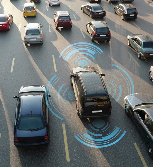
Fast forward a hundred years. Radar has been used for decades to calculate the velocity, range, and angle of objects on land, sea, and in the air. On the road, radar is playing a key role of Advanced Driver Assistance Systems (ADAS), which constitute an intermediate stage in the development of self-driving vehicles.
Radar is particularly useful in two ADAS technologies: automatic emergency braking system (AEBS) and adaptive cruise control (ACC). These applications use long-range radar (LRR) systems with ranges of 80 m to 200 m or greater. Current LRR systems operate in the 77 GHz frequency band (76 – 81 GHz). This frequency has several advantages for automotive use: the wide bandwidth available improves accuracy and object resolution; with a wavelength of 3.9 mm, the antenna can be small; and atmospheric absorption limits interference with other systems.
Principles of FMCW Radars
The broadband Frequency Modulated Continuous Wave (FMCW) radar has become the dominant technology for automotive use because it combines high resolution in range and depth perception, with the detection of objects like pedestrians and bicycles in a small radar cross-section.
In an FMCW radar, both transmitter and receiver operate continuously; the transmitter deploys a sinusoidal carrier with a frequency that increases then decreases periodically over time- a sequence known as a chirp.
The TX signal travels to the target object and is reflected back to the receiver; the difference in frequency between the RX and current TX signal is proportional to travel time, can be used to measure distance, and distinguish between different objects.
Figure 2 shows the received FMCW signals. Each one is a delayed and attenuated reflection of the transmission corresponding to a different object: in the frequency domain, each object is a tone with a frequency, fb, proportional to the object’s distance from the source, R.
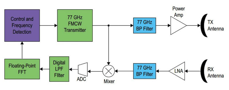
Figure 3 shows a conceptual block diagram of an FMCW radar. The radar detects multiple objects and their respective distances by performing a fast Fourier transform (FFT) on the IF beat-frequency signal, and identifying the tones corresponding to each object.
An object’s relative velocity is determined by comparing the Doppler frequency shifts of the chirp’s increasing and decreasing frequency portions: Intel PSG (formerly Altera) has a white paper with a detailed discussion.
Numerous automotive Tier 1 suppliers and their semiconductor partners have produced reference designs for LRR systems. Figure 4 shows a representative example from Infineon; Texas Instruments, NXP, and STMicroelectronics are also focusing heavily on semiconductors for ADAS and autonomous vehicles.
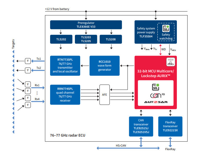
Three components form the radar transceiver’s heart as seen in Figure 4: the RTN7735PL three-channel transmitter and local oscillator; RRN7745PL/46PL four-channel receiver; and RCC1010 radar companion chip with programmable modulation waveform generation and PLL frequency control.
The transmitter and receiver die are packaged in Infineon’s Embedded Wafer Level Ball Grid Array (eWLB) package: multiple units can combine to form a scalable platform for long- and mid-range systems in conjunction with options such as the RPN7720PL dual power amplifier for increased output power.
The Aurix microcontroller is Infineon’s family of devices optimized for safety-critical automotive applications. The TC297TA, for example, includes a trio of 32-bit superscalar CPUs running at 300 MHz with eight MB Flash memory, DSP functionality, and multiple channels of both delta-sigma and SAR analog-to-digital conversion. The microcontroller runs under AUTOSAR (AUTomotive Open System ARchitecture), an industry-standard software architecture for automotive electronic control units.
The Aurix architecture and TLF35584 power supply include safety features, helping the system meet Automotive Safety Integrity Level (ASIL) level D requirements. ASIL is a risk classification scheme defined by the ISO 26262 (Functional Safety for Road Vehicles) standard; ASIL D is the highest level, and applies to equipment where a malfunction can risk severe or fatal injury.
An Automotive Radar Solution: The Bosch LRR4
Bosch’s LRR4 radar system (Figure 5) exemplifies a complete packaged solution from a Tier 1 automotive supplier, and even includes a heated lens for combating poor weather conditions.
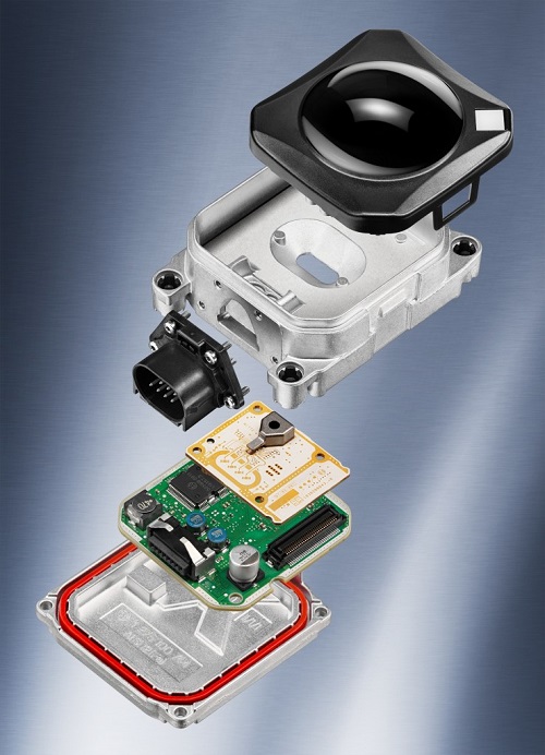
Bosch’s LRR4 radar system (Figure 5) exemplifies a complete packaged solution from a Tier 1 automotive supplier, and even includes a heated lens for combating poor weather conditions.
The LRR4 is a monostatic (transmitter and receiver collocated) multimodal radar sensor, with six fixed radar antennas operating in the 77 GHz frequency band. The central four antennas have a narrowly focused ±6° beam pattern to detect objects up to 250 m in front of the vehicle, while minimizing interference from traffic in adjacent lanes.
For medium-range applications (up to five meters), the LRR4’s outer two antennas expand the field of view to ±20° so that the system can quickly detect other vehicles entering or leaving their lane. The LRR system can distinguish up to 24 separate objects.
Internally, the sensor contains two printed circuit boards (PCBs): the radio-frequency (RF) board includes planar antennas and an Infineon 77 GHz SiGe transmitter and receiver; the control and interface board relies on microcontrollers from NXP and STMicroelectronics, plus Bosch power management ICs.
Challenges for LRR Designers: Truck, Pedestrian…. Or Soda Can?
Compared to LIDAR and optical sensing technologies, radar is largely insensitive to environmental conditions like fog, rain, wind, darkness, or bright sun, but technical challenges remain.
A radar system’s ability to detect an object largely depends on reflection strength: this is influenced by factors such as the object’s size, distance, absorption characteristics, reflection angle, and transmission power.
A vehicle or truck might have a large reflection, but an ADAS-equipped vehicle must also account for pedestrians and motorcycles, which aren’t only smaller in size but have relatively few hard or metallic shapes to reflect radar signals. In a busy environment, the reflection from a truck can swamp that from a motorcycle; a small child standing next to a vehicle can become “invisible” to a radar receiver. Conversely, an object like a soda can may produce a radar image far out of proportion to its size.
Increasing automation levels will require a system that can analyze complex scenarios and correctly respond to multiple potential hazards. To meet these challenges, ADAS designers are combining the inputs from radar, LIDAR, ultrasonic, and visual sensors, to provide data individual sensors working independently are unable to generate. Known as sensor fusion, this process combines the benefits of different sensors and measurement techniques in the most effective way possible to increase the reliability, range, and accuracy of overall results. Aggregated data then enables the software to form a detailed map of the vehicle‘s surroundings.
