The reliability of board-mounted dc/dc converters is important to understand and quantify. It’s a measure of the frequency of system or device failures as a function of time. Reliability is the observed failure rate and is defined as either the time between two failures (in hours), called the Mean Time Between Failures (MTBF), or the time until the first failure (also in hours), called the Mean Time To Failure (MTTF). Sometimes reliability is quantified by the MTBF figure’s reciprocal, based on 109 hours, called Failures In Time (FITs): FIT = 109/MTBF.
Every device has a failure rate, λ, which is the number of units failing per unit time—the failure rate changes throughout the device’s life in a predictable way. When plotted as failure rate versus time, it is often called the reliability bathtub curve. It illustrates the sum of the Early “Infant Mortality” Failure rate, plus the Constant (Random) Failure rate throughout the life of the product, plus the end-of-life Wear Out Failure rate.
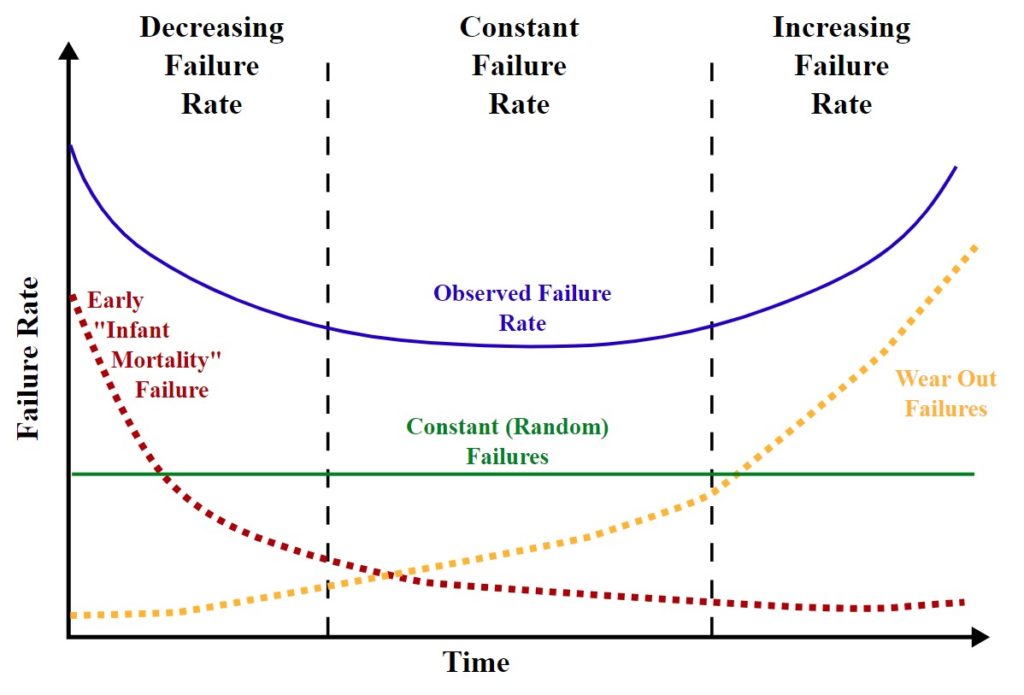
Decreasing failure rates, declining λ, are experienced during the first period of a product’s life when so-called “infant mortality” occurs, caused by material defects or manufacturing errors that were not caught in final testing and inspection. Most infant mortality for board-mount dc/dc converters occurs in the first 24 hours of operation.
In electronics, the Arrhenius equation is used to determine a component’s projected life operating at a given temperature. It is adapted from chemistry, where it measures reaction rate in relation to temperature, and it leads to the observation that lowering the temperature by 10°C will double product reliability. Conversely, increasing the operating temperature accelerates the failure rate of electronics.
The Arrhenius equation is the justification for burning in electronic devices and systems. For example, operating just-manufactured dc/dc converters at full load and elevated temperatures in a burn-in chamber for about 4 hours can eliminate many infant mortality failures. Often, 40 or 50 °C is used for burn-in, and sometimes higher temperatures and elevated humidity are used to increase stress further. High-reliability dc/dc converters typically receive a 24-hour burn-in.
During product and system development, accelerated stress testing systems for Highly Accelerated Life Testing (HALT) and Highly Accelerated Stress Screening (HASS) can find product design weaknesses. Performing HALT and HASS improves product reliability by maximizing lab efficiencies while reducing costs associated with warranties and recalls. HALT and HASS use temperature, and vibration stresses to eliminate design problems, develop a robust product, and screen out early product failure issues. HALT and HASS determine product operating and destruct limits as stresses are applied to the product while being functionally tested and continuously monitored for failures.

During most of dc/dc converters’ life, after the Infant Mortality period, they experience a constant failure rate, λ, and the reliability curve is essentially flat. The time period that the constant failure rate lasts is dependent on various factors such as the inherent stresses of the application environment, the quality of the components used, the manufacturing quality of the dc/dc converter, and so on. Increasing failure rates are experienced during wear out at the end of the useful product life.
Predicting reliability
The two most common tools for predicting reliability are MIL-HDBK-217 and the Telcordia Reliability Prediction Procedure SR-332. These and other reliability predictions are built in part on the Arrhenius equation. MIL-HDBK-217 was originally developed by the U.S. military and produces MTBF and MTTF figures, while Telcordia SR-332 was developed for the telecommunications industry and produces FIT figures. Currently, MIL-HDBK-217 is the most widely used reliability calculation methodology.
Reliability can be predicted and quantified in several ways, using a Parts Count Analysis (PCA), a Part Stress Analysis (PSA), or with demonstrated field data. Each of these methods of quantifying reliability has specific uses for power system designers. PCA requires the least data and is typically used during the product development process. PCA analysis produces an estimated product failure rate, λP, and is based only on the bill of materials and the anticipated use, enabling the calculation of the MTBF for a product that is still being designed: λP = (Σ NC λC) (1 + 0.2 πE) πF πQ πL (equation: RECOM)
Where:
NC = number of parts (per component type)
λC = failure rate of each part taken from a database
πE = application-specific environmental stress factor
πF = hybrid function stress caused by component interaction
πQ = screening level for standard parts or pre-screened parts
πL = maturity factor is this a proven design or a new approach
The PCA is calculated for each component used, and the total reliability prediction is derived by adding up all of the individual predictions.
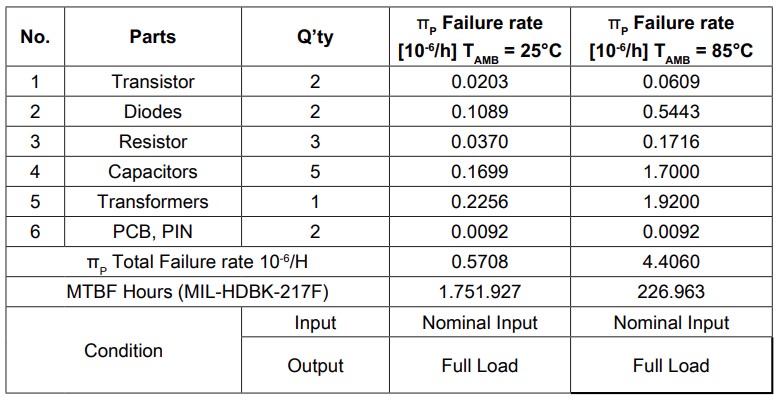
The MIL-HDBK-217F PSA method provides constant failure rate models based on curve-fitting the empirical data obtained from field operation and testing. Like the PCA analysis, the PSA model has a constant base failure rate modified by environmental, temperature, electrical stress, quality, and other factors. But the PSA method assumes there are no modifiers to the general constant failure rate. Although it is widely adapted to devices such as board-mounted dc/dc converters, the MIL-HDBK-217 methodology was originally intended to only provide results for parts, not for equipment or subsystems.
The main concepts in MIL-HDBK-217 and Telcordia SR-332 are similar, but Telcordia SR-332 also has the ability to incorporate burn-in, field, and laboratory test data for a Bayesian analytical approach. Bayesian inference is a method of statistical inference in which Bayes’ theorem is used to update the probability for a hypothesis as more evidence or information becomes available.
System design considerations for reliability
DC/DC converter failure rate analysis is focused on the operating temperature, input voltage, and output power to estimate overall stress. Good thermal management is the most important aspect of designing reliable systems using board-mounted dc/dc converters. Good thermal management begins with understanding how the efficiency of the converter impacts system performance. Derating is always a good practice. But what to derate? The nominal performance specifications are not always the best choice for derating. Instead of looking at the specified typical ratings, looking at worst-case ratings, especially for efficiency, are often a good place to start.
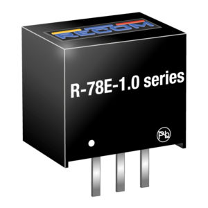
Efficiency is typically specified at 25°C, but it is common for systems to operate at higher temperatures. As temperature rises, losses for power semiconductors and circuit board traces can increase. The temperature coefficient of copper is +0.393%/°C. If the temperature increases 1°C above room temperature, the resistance will increase by 0.393%. And converter efficiency varies with the input voltage, decreasing as the input varies from the nominally specified voltage.
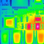
As a result, thermal mapping during system development is necessary to identify hot spots and other areas of concern from a thermal standpoint. Thermal mapping enables the design of the correct thermal management system for the specific operating environment. It helps to identify areas that need to be monitored (measured) during system operation. Thermal mapping can also identify spot heat sources such as linear regulators that may need to be replaced with higher efficiency board-mounted dc/dc converters such as switching regulators.
While thermal management is the primary concern, the characteristics of the input voltage should not be overlooked. Operating for extended periods at high or low lines will reduce reliability, so will surges, spikes, and electrostatic discharge (ESD) on the input. The use of protection devices on the converter’s input can go a long way toward improving system reliability.
That concludes this FAQ series on board-mounted dc/dc converters. Part one focused on “specifying board-mounted dc/dc converters,” part two looked into “thermal management considerations for board-mounted dc/dc converters,” and part three explored “EMC/EMI design and the use of board-mount dc/dc converters“.
References
Bathtub curve, Wikipedia
Critique of MIL-HDBK-217, National Academy of Sciences
DC/DC Book of Knowledge, RECOM

