• Skip to primary navigation
  • Skip to main content
  • Skip to primary sidebar
  • Skip to footer

Electrical Engineering News and Products

Electronics Engineering Resources, Articles, Forums, Tear Down Videos and Technical Electronics How-To's

  • Products / Components
    • Analog ICs
    • Connectors
    • Microcontrollers
    • Power Electronics
    • Sensors
    • Test and Measurement
    • Wire / Cable
  • Applications
    • Automotive/Transportation
    • Industrial
    • IoT
    • Medical
    • Telecommunications
    • Wearables
    • Wireless
  • Resources
    • DesignFast
    • Digital Issues
    • Engineering Week
    • Oscilloscope Product Finder
    • Podcasts
    • Webinars / Digital Events
    • White Papers
    • Women in Engineering
  • Videos
    • Teschler’s Teardown Videos
    • EE Videos and Interviews
  • Learning Center
    • EE Classrooms
    • Design Guides
      • WiFi & the IOT Design Guide
      • Microcontrollers Design Guide
      • State of the Art Inductors Design Guide
    • FAQs
    • Ebooks / Tech Tips
  • EE Forums
    • EDABoard.com
    • Electro-Tech-Online.com
  • 5G

Computing platform verifies network ICs prior to silicon

April 20, 2021 By Martin Rowe

The Veloce hardware-assisted verification system from Siemens Digital Industries Software lets engineers verify digital IC designs while they are still software. Processing power ranges from a single board to a multi-chassis rack.

Digital IC designs such as those used in network routers and switches perform many functions and may contain more than a billion logic gates. Performing verification on silicon is costly and time consuming. Performing that verification when the IC is still in Register Transfer Level (RTL) form, however, means you can evaluate the design, make changes in software, and quickly re-run tests.

To find and make such changes, you need an environment that emulates actual conditions. To verify designs used in, say 5G fronthaul applications, you need enough computing power to run your entire RTL code under simulated input and output conditions.

The Veloce hardware-assisted verification system from Siemens Digital Industries Software consists of a family of computers that range from a single-board desktop system (Veloce proFPGA) to a chassis of computing boards (Veloce Primo) to full rack-mount systems of multiple chassis (Veloce Strato+). At the highest level, that’s supercomputing power (Figure 1).

Veloce

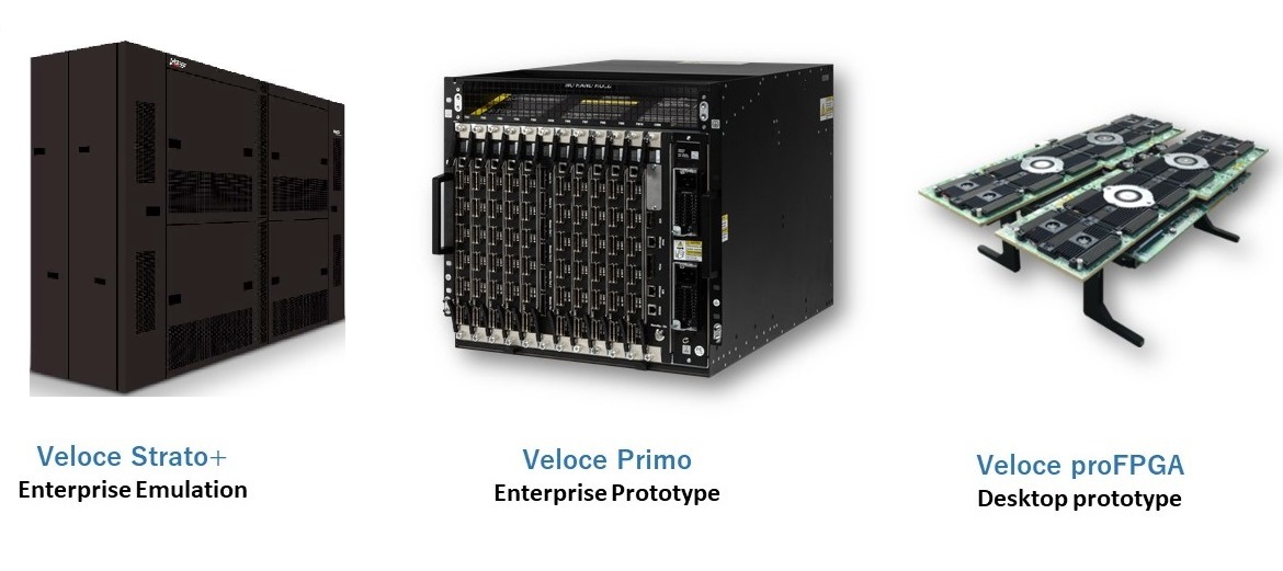
Figure 1. The Veloce hardware-assisted verification platform from Siemens Digital Industries Software ranges from a single computing board to a rack of many boards in chassis.

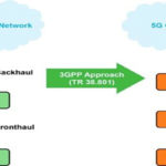
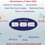
The system takes RTL code from the user, wraps it in a virtual environment, and tests the design. It virtualizes the network environment’s protocols through models. “We can virtualize a complete 5G front-haul communication network including Ethernet, CPRI, eCPRI, and Open RAN” said Jean-Marie Brunet, Sr. Director Product Management/Engineering to 5G Technology World. “By having virtualized models of silicon, you can change the models as the specs change.”

For verifying network ICs, you’ll also need stimulus and that means virtualized test equipment. Figure 2 shows network testers from Keysight, Siemens, and Spirent that generate traffic based on RFC 2889 and RFC 2544. The Veloce system virtualizes those testers and adds the necessary transport protocols to put the virtual IC into its environment from which it can evaluate the virtual device under test. On the back end, the system takes the virtual waveforms from the DUT and provides test results such as dropped packets, packet latency, throughput, and bandwidth.

Figure 2. The platform emulates network traffic for an RTL design and produces test data.

In addition to emulating 5G networks, the Veloce system can verify Wi-Fi IC code at baseband. You can, of course, use the platform to verify other types of digital IC designs such as computational storage devices.

Because the Veloce system is modular, you can combine the computer chassis into systems. For example, the rack shown in both figures consists of your chassis, but you can configure smaller systems as well. According to Brunet, a rack such as those shown can handle RTL code for design of two billion gates. A single chassis, which can contain up to 16 computing boards, might handle design with under 200 million gates. A single board contains 24 processors.

You may also like:

  • Open RAN
    Open RAN functional splits, explained

  • Roadmap helps governments promote, fund, and implement 5G open RAN

  • Why 5G O-RANs need compliance and interoperability testing

  • Video: Panel highlights Open RAN technology and policy

  • Open RAN has rewards, but comes with risks
DesignFast Banner version: 23aa529f

Filed Under: 5G, Applications, Telecommunications Tagged With: siemens

Primary Sidebar

EE Training Center Classrooms

EE Classrooms

Featured Resources

  • EE World Online Learning Center
  • CUI Devices – CUI Insights Blog
  • EE Classroom: Power Delivery
  • EE Classroom: Building Automation
  • EE Classroom: Aerospace & Defense
  • EE Classroom: Grid Infrastructure
Search Millions of Parts from Thousands of Suppliers.

Search Now!
design fast globle

R&D World Podcasts

R&D 100 Episode 7
See More >

Current Digital Issue

April 2022 Special Edition: Internet of Things Handbook

How to turn off a smart meter the hard way Potential cyber attacks have a lot of people worried thanks to the recent conflict in Ukraine. So it might be appropriate to review what happened when cybersecurity fi rm FireEye’s Mandiant team demonstrated how to infiltrate the network of a North American utility. During this…

Digital Edition Back Issues

Sponsored Content

Positioning in 5G NR – A look at the technology and related test aspects

Radar, NFC, UV Sensors, and Weather Kits are Some of the New RAKwireless Products for IoT

5G Connectors: Enabling the global 5G vision

Control EMI with I-PEX ZenShield™ Connectors

Speed-up time-to-tapeout with the Aprisa digital place-and-route system and Solido Characterization Suite

Siemens Analogue IC Design Simulation Flow

More Sponsored Content >>

RSS Current EDABoard.com discussions

  • Series and Shunt S2P file of inductor or capacitor
  • kt/c noise of sample and hold
  • Noise analysis of sample and hold amplifier
  • Correct measurement of process variations
  • 3D FDTD - how do I compute number of variables and required number of iterations?

RSS Current Electro-Tech-Online.com Discussions

  • A high-speed ADC which reads upon trigger
  • None existant errors (MPLAB X)
  • software PWM
  • Passthrough charging-simple but impossible to achieve?
  • PCB Photo sensitizing options

Oscilloscopes Product Finder

Footer

EE World Online

EE WORLD ONLINE NETWORK

  • 5G Technology World
  • Analog IC Tips
  • Battery Power Tips
  • Connector Tips
  • DesignFast
  • EDABoard Forums
  • Electro-Tech-Online Forums
  • Engineer's Garage
  • Microcontroller Tips
  • Power Electronic Tips
  • Sensor Tips
  • Test and Measurement Tips
  • Wire & Cable Tips

EE WORLD ONLINE

  • Subscribe to our newsletter
  • Lee's teardown videos
  • Advertise with us
  • Contact us
  • About Us
Follow us on TwitterAdd us on FacebookConnect with us on LinkedIn Follow us on YouTube Add us on Instagram

Copyright © 2022 · WTWH Media LLC and its licensors. All rights reserved.
The material on this site may not be reproduced, distributed, transmitted, cached or otherwise used, except with the prior written permission of WTWH Media.

Privacy Policy