Motors that power cooling fans tend to be either brushless motors or induction motors. Here we examine the key differences in the construction of these two motor types and explain the reason for the striking differences in energy efficiency between the two types.
Brushless motors are sometimes called electronically commutated motors. Here commutation refers to the act of switching the electrical connection from one motor winding to the next one. Motor windings in a dc motor generally sit in the stator or stationary portion of the motor. Then the rotor contains a magnet with alternating poles. (A dc motor with the magnets in the rotor is sometimes called an outrunner. There are other possible configurations but they are not as widely used as outrunners.)

A rotor from a brushless dc fan motor showing the magnet. Brushless motors with the magnets in the rotor are called outrunner motors.
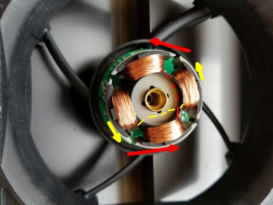
A four-pole dc brushless motor stator (from an Orion fan). The red arrows indicate the direction one set of poles pull the rotor. Simultaneously, the other set of poles (yellow arrows) push on the rotor.
The brushless dc motor uses an electronic controller to sequentially energize the stator windings, turning them into electromagnets, in a sequence that turns the rotor. To start, one set of coils (that is, a coil and the coil located 180º away from it) would be energized to become electromagnets. This causes the opposite poles of the rotor and stator to be attracted to each other. As the rotor nears the energized coil, the next coil is energized and the coil nearest the rotor pole is switched off. As the rotor rotates near the next coil on the stator, the coil nearest the rotor pole is switched off. This sequence repeats as the rotor runs. The point to note is that there is always one set of coils pulling the rotor, causing it to rotate.
For simplicity, this explanation treats only one set of coils at a time. However, more than one set of coils at a time is energized. In reality, the set of coils behind the set pulling on the rotor is energized in a way that pushes on the rotor rather than pulls it. So there is a combined effect of pulling and pushing on the rotor which gives this motor a lot of efficiency. The combined effect is that most of the coils in the stator act on the rotor nearly all the time. And high efficiency is one of the reasons you see fans built with electronically commutated dc motors.
One aspect of brushless motor operation is the necessity of knowing the position of the magnetic poles in the rotor. To fire the right stator coils at the right time, the controller must sense the position of the rotor. The controller reads the rotor position sensor to decide what coils to energize.
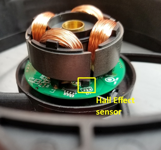
The Hall sensor visible on an Orion brushless dc fan motor.
The usual way to sense the rotor position is with a Hall Effect sensor. It’s also possible to measure the back-EMF in the undriven coils to infer the rotor position, eliminating the need for separate Hall effect sensors, but that scheme is a bit more complicated.
Brushless motors are typically 85 to 90% efficient largely because most of the energy going into the coils actually moves the rotor. We can contrast the dc brushless motor with another type found in fans, the shaded pole-type induction motor.
Induction motors get their name because electromagnets in the stator induce magnetism in the rotor. They induce magnetism in the rotor because, unlike the rotor in a brushless dc motor, the rotor in an induction motor contains no magnets.
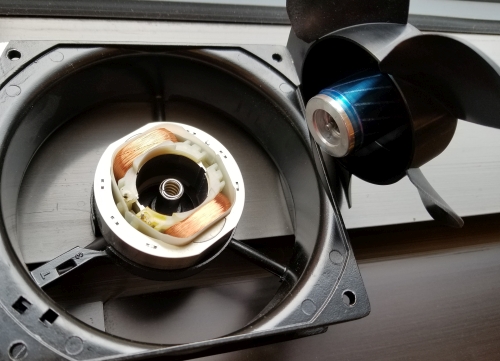
A shaded pole induction motor and the squirrel-cage rotor. These are from an Orion fan.
Though they are difficult to spot, here are the tell-tale slots in the laminations for the shading coils of this shaded-coil fan motor.
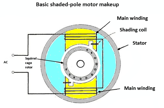
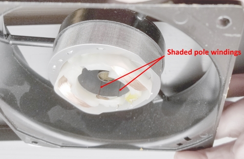
The term shaded pole comes from the use of a separate small winding, called a shading coil, in the stator. The electromagnets in the stator are formed by coils around steel laminations. The shading coil is wound around a small section of the laminations. When ac is supplied to the main winding, a portion of the resulting magnetic flux links to the shading coil. This induces a current in the shading coil which behaves like the secondary of a transformer. The induced current, in turn, produces its own (weak) magnetic flux which lags the magnetic flux in the main portion of the stator. Consequently, there is a time and space displacement between the two fluxes. This time and space displacement sets up the conditions for a rotating (or shifting) magnetic field. The rotating magnetic field is what starts and keeps the rotor turning.
Some shaded pole motors don’t use a shaded coil. Instead, they use a small break in the laminations which can be enough to create the lagging magnetic field necessary for turning the rotor.
The nice thing about shaded pole motors is that they are inexpensive because they have a pretty simple construction. But the problem is that they are inefficient, largely because of the lossy linkage between the shaded coil and main winding. The efficiency of shaded pole motors generally is only between 15 and 30%. And the power factor is rather low as well.
A low power factor and efficiency is probably ok for applications where there is only one small fan (shaded pole motors are generally 40 W or less). But consider an application like a data center containing racks and racks and racks and racks of severs, and each of those servers has its own fan. It is not advisable to have hundreds or even thousands of fans all operating at only 30% efficiency. These applications really can benefit from using the brushless motor technology and the 90% efficiency it entails.

Leave a Reply
You must be logged in to post a comment.