by John Perzow, Wireless Power Consortium
When it comes to energy efficiency, there are significant differences in competing wireless charging methods.
There are a lot of claims made about the energy efficiency of wireless charging schemes. Engineers are understandably skeptical. After all, it is hard to envision how two induction coils sitting some distance away from each other could engage in energy efficient charging.
Fortunately, there is meaningful data available about wireless charging efficiency. It serves important purposes by helping decision makers assess different standards, and it enables informed choices regarding the deployment of a given standard. Additionally, efficiency data helps engineers and product designers determine which user benefits are worth the “cost” in terms of efficiency.
That said, it is true that there’s limited public data comparing the real-world power-transfer efficiency of different wireless power standards.
Wireless chargers are essentially power supplies, and power supply engineers generally assess the quality of a power supply by its efficiency over a load range. Consequently, wireless charging systems are often characterized by their efficiency at a given load current. This industry convention results in misleading and inaccurate characterizations of the performance of a power supply that is designed specifically as a wireless charging system.
It is possible, however, to specify the efficiency of a wireless charger more accurately by comparing the total energy used by the battery over a complete charge cycle, to the energy into the wireless power transmitter over the same charge cycle.
Wireless charging for mobile consumer electronics has reached mainstream adoption, and a host of approaches in various stages of development and deployment have emerged that offer a range of benefits. Unfortunately, none of the various approaches are compatible nor are they interoperable. As designers consider incorporating wireless charging technology into their products, they must assess the benefits and tradeoffs of the available or emerging standards. The key tradeoff is efficiency versus a purported benefit. Without an industry consensus on how to measure efficiency, a basic design tradeoff cannot be assessed.

Here are the tradeoffs of the various magnetic induction-based wireless charging approaches. As of the writing of this article, there were no Rezence systems available in the market. Claims of Rezence benefits are derived from publically-available marketing materials.
Why different approaches
Closely-coupled configurations make up the lion’s share of the demand for wireless chargers. The classic example of this approach is that of a smartphone sitting in its wireless charging stand on a desktop. This mode results in maximum power transfer efficiency, lowest EMI/RFI/EMF and lowest cost.
Loosely-coupled configurations are those characterized by a power transmitter mounting under, say, the surface of a desk, countertop or other furniture. The device-to-be-charged sits somewhere on the table surface. Loose coupling approaches are useful in after-market installations of existing furniture and represent about 5 to 10% of the volume demand for wireless chargers. Of course, a loosely-coupled system has a greater charging distance. The cost of the approach is lower efficiency and a higher bill of materials. It is also more difficult to contain the EMI/RFI/EMF in a loosely-coupled system that is operating at high frequency.
With these two charging approaches in mind, consider the problem of useable efficiency data. One difficulty is the lack of an agreed measurement method. We have seen claims of coil-to-coil or “dc-in” to “dc-out” efficiency numbers, but these do not predict overall system performance.
For example, both closely-coupled (not operating in resonance) and loosely-coupled (operating in resonance) systems can hit coil-to-coil efficiencies in excess of 90%. This does not imply that the overall system efficiency is 90%, however, so this data point can be misleading.
Measuring efficiency into a dc load at the output of the rectified receiver can also result in a high reading (greater than 85% in the closely-coupled system and 75% in the loosely-coupled system). But again, this should not be construed as a predictor of overall system efficiency. Measurements taken at the output of the power supply regulator can be a good proxy for real-world efficiency measurements, but output voltages and resistors used to simulate a real load must be selected to mimic the battery-charge cycle.

Measuring efficiency into a dc load at the output of the rectified receiver (dc input to dc out A in this figure) can also be high (>85% in the closely-coupled system and 75% in the loosely-coupled system). But this should not be construed as a predictor of overall system efficiency. Measurements at “dc out B” can be good proxies for realworld efficiency measurements, but output voltages and resistors need to be selected carefully to mimic the battery-charge cycle.
The Wireless Power Consortium, the organization behind the primary wireless charging standard called Qi (pronounced “chee”), commissioned a study at Colorado State University that examined the total energy efficiency between two types of wireless chargers: a loosely-coupled system with coils operating in mutual resonance at 6.78 MHz, and a closely-coupled system operating out of resonance at a switching frequency of 110 to 205 kHz. Both cases used a typical cellphone battery-charging configuration. The dc-to-dc post-regulator and the battery charger used were both switching topologies and selected for their best-in-class efficiency of 90% or better. A 2,100-mAh battery model was developed, which determined the load profile.

Researchers at Colorado State University used this topology in measuring the total energy efficiency of loosely-and closely-coupled wireless charging systems. The dc-to-dc post-regulator and the battery charger used were both switching topologies and selected for their best-in-class efficiency of 90% or better. A 2,100-mAh battery model was developed, which determined the load profile as depicted at right.
As wireless charging systems let the user randomly place the receiver (phone) on the charging surface, the test also mapped a 3D spatial dependence of the transfer efficiency for each system. In both cases, the receiver was placed at the optimal X-Y position and at a 5-mm coil-to-coil Z-distance. The efficiency measurements were then taken over a typical charge cycle (5 to 95%) of the battery. The results of the study went into a proposal for a technique to accurately assess the power transfer-efficiency of a wireless charging system.

Researchers at Colorado State University mapped a 3D spatial dependence of the transfer efficiency for both loosely (right) and closely (left) coupled wireless charging systems. For ease of viewing, only half of the charging area is depicted in the map of tightly coupled efficiencies.
The first proposal to come out of this work is that efficiency should be calculated as total energy into the battery divided by total energy into the transmitter over the battery charge cycle.
When a wireless power receiver directly drives a resistive load, the power transfer from the input of the transmitter to the resistive load is quite efficient, in some cases exceeding 90% for low-frequency systems. However, tests show the total system efficiency can severely degrade when the receiver is configured for a typical battery-charging application. This is particularly true for high-frequency systems.
We attribute this power-transfer degradation to two primary mechanisms: (a) The high-frequency system requires a relatively high receiver antenna impedance. And the range of receiver output voltages forces the (time-averaged) input impedance of the dc regulator into a point where the wireless transfer process is less efficient. (b) Switching losses in the high-frequency transmitter output transistors. Integrating the energy delivered to the battery and energy put into the transmitter over the time of a charge-cycle enables a real-world assessment of system efficiency.
The second proposal is that power-transfer efficiency measurements should be taken as a spatial average. Given the flux map characteristics of a given transmitter, the system efficiency can vary significantly over the charging area or charging volume. To mimic real-world use, efficiency measurements should be taken in 2-mm increments over the load profile. If appropriate output impedances and voltages are used, it is easy to calculate the total energy for a charge-cycle for each spatial cell.
Finally, the tests indicate it’s best to calculate total energy over a battery-charge cycle. The battery load profile describes the time-dependent battery voltage and current during a charge cycle, VB(t) and IB(t) and calculation of energy into the battery, EB, is as follows: At any time t in the charge-cycle, the battery receives an increment of energy from power P in time dt:

Therefore, calculation of the energy delivered to the battery over a cycle is the integral of power, which for a discrete-time calculation, becomes a simple sum:

where Δt is the incremental step and tn ranges over the duration of the charge cycle. In our calculations, Δt is one minute and tn ranges from 1 to 150 (the programmed charge time). In a similar manner we can use efficiency versus load (battery) current, η (IB), to calculate the incremental energy source input dES that provides battery energy dEB as a function of current draw by the battery:

Thus charge cycle efficiency is obtained from:

Efficiency comparisons
The point of this study is to make public the tradeoffs between different wireless charging approaches. The closely-coupled Qi system was designed from the start to be as efficient and inexpensive as possible. This approach excels in most consumer applications where the transmitter and receiver lie in close proximity. Examples include charging stands for bedside tables, desktop charging pads, and through-hole chargers in public locations.
There are examples where extended distance between the receiver and transmitter is necessary, and it may be appropriate to sacrifice some efficiency in these applications. After-market furniture installations are the typical example. The WPC approach has always been to give OEMs the ability to use whichever approach is most appropriate while maintaining full interoperability between Qi devices.
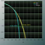
When using the charge-cycle efficiency calculation described above, it is possible to plot total energy versus time over the battery-charge cycle for each spatial cell in the charging area or charging volume. The closely-coupled system consumed 50% less energy than the loosely-coupled system over the course of a 2,100-mAh battery charge.

A plot of the energy used by the battery and energy consumed by the two different wireless charging transmitters provides a feel for relative amounts of energy lost in loosely and closely-coupled charging systems. The closely-coupled system consumed 50% less energy than the loosely-coupled system over the course of a 2,100-mAh battery charge.
The high-frequency, loosely-coupled and the low-frequency, closely-coupled systems have different loss profiles. Although the loosely-coupled system we tested uses gallium-nitride output transistors and zero-voltage switching, the high operating frequency of the architecture results in significant transmitter switching loss (greater than 800 mW). The value of operating in resonance, however, becomes evident where even at 20 mm, the loosely-coupled system shows relatively little coupling loss.

As you might expect, closely-coupled charging systems have a higher power transfer efficiency than loosely-coupled versions.
Another observed loss factor would best be described as a maximum power-point transfer (MPPT) problem. The characteristic impedance of the loosely-coupled receiver antenna (about 24 Ω) is not well-matched to the load impedance (3.5 to 32 Ω) of the battery. Most systems will optimize this power-point for the maximum load condition (4.2 V, 1. 2 A, 3.5 Ω), but the total energy used is impacted by the significant time spent in lower load, higher impedance output conditions.
Armed with real data, it’s easy to see that it does not make sense to use a less efficient, high-frequency, loosely-coupled system when a closely-coupled approach will do the job. Conversely, it is appropriate at times to sacrifice some efficiency when a larger Z-distance is needed. That is why a wireless power specification that meets all market requirements must support both closely- and loosely-coupled approaches.
References
Wireless Power Consortium
www.wirelesspowerconsortium.com