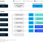
The first two FAQs in this series, “Class D Amplifiers for High-Efficiency Switched-Mode Sound” and “Class D Audio – Why Now?” focused on basic Class D amplifier topologies, modulation techniques, general component and technology advancements that have made Class D amplifiers an increasingly viable option, and the evolving tradeoffs between silicon and GaN power devices. This final installment in this three-part FAQ series will delve into design and specification considerations when using Class D amplifiers.
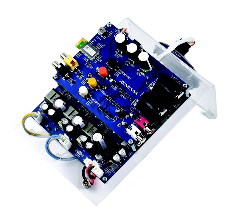
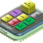
Class D amplifier reference design with GaN FETs from Efficient Power Conversion (Image: Renesas)
Eradicating EMI
Expecting to eradicate electromagnetic interference (EMI) may be overly optimistic for a high-frequency power switching Class D amplifier design. But managing and controlling EMI is possible, and can also be very important for noise-sensitive environments such as automotive audio systems. EMI can be controlled in several ways when dealing with Class D amplifiers.
At the system level, it is important to keep the connection from the amplifier to the speakers as short as possible. Any circuit board traces or a wiring harness will act as an antenna. Minimizing the length of these antennae will also minimize the radiated EMI. Particularly in the case of filterless Class D amplifiers, those connections between the amplifier and the speaker are likely to be the primary source of radiated EMI. As always, when dealing with switching power converters, good overall EMI design practices such as paying attention to the location of ground planes, the use of properly placed decoupling capacitors, and including ferrite beads on the output leads, are wise measures.
In addition, the application of spread-spectrum technology to Class D amplifiers can help mitigate EMI. With this approach, the switching frequency of the amplifier is randomized (or dithered), typically over about a 10% range. In a fixed-frequency design, the spectral energy is concentrated at the switching frequency and its harmonics. The use of spread-spectrum modulation effectively spreads the RF energy of the output signal. While the total amount of RF energy (EMI) in the output remains the same, the energy is redistributed over a much wider bandwidth, reducing the energy peaks. This reduces the density of the energy and simplifies filtering.
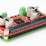
The wideband output spectrum is shown for the MAX9700 using a fixed switching frequency, (source Maxim Integrated Products)
The wideband output spectrum is shown for the MAX9700 using a fixed switching frequency (Image: Maxim Integrated Products)
Dealing with distortion
Major sources of distortion in Class D amplifiers are the deadtime in the output stage, nonlinearities in the modulation scheme, and non-optimal feedback mechanisms. Deadtime protects against the slight differences in switching characteristics between the power switches in the output and the variances in the respective drive circuits, which could inadvertently result in simultaneously turning both devices on. But adding deadtime also adds a nonlinear timing error, which results in cross-over distortion of the audio content in the signal. The shortest deadtime that prevents shoot-through also minimizes the associated distortion.
Feedback is used in both traditional linear amplifiers and Class D amplifiers to clean up the sound and reduce THD. THD is measured under static conditions, and there is a tradeoff between THD and dynamic response. Music, in particular, is dynamic, and too much feedback reduces the dynamic response of the amplifier. As a result, there is a balance to be achieved between low THD and the needed level of dynamic response.
This is an instance where using GaN switching devices can be beneficial. GaN provides higher linearity in the open loop and needs less feedback to achieve a given level of THD. As a result, GaN-based Class D amplifiers can more easily deliver low THD and high dynamic response, resulting in richer-sounding music.
Sound protection
As with all electronic power systems, Class D amplifiers require comprehensive protective functions to ensure reliable operation. A summary of the most critical output protection functions includes:
- Thermal shutdown – thermal sensing in the power stage can be implemented that shuts down the amplifier at elevated temperatures. Or, the control circuitry may reduce the output power (volume of the sound) to reduce power dissipation and keep the temperature within acceptable limits.
- Overcurrent protection – current sensing on the output of the power transistors is necessary. As with thermal protection, this can take the form of a complete shutdown in the case of excessive currents, or in more complex designs, it can act as a current limit enabling continuous operation of the amplifier by limiting short-duration high-current transients.
- Undervoltage protection – also called undervoltage lockout, this function disables operation when the voltage drops below a preset level to protect the amplifier from damage. This can be especially important in battery-powered applications.
- Deadtime protection – sometimes called “break-before-make” this controls the turn-on timing of the output transistors to prevent conduction overlap, which would result in shoot-through currents and could result in transistor overheating, damage, or even destruction. This is an important design consideration. Too much deadtime can result in on-linearities in the output, degrading the audio quality of the amplifier.
References
3-in-1 Audio System Reference Design, Renesas
Class D audio amplifiers: what, why and how, Analog Devices
Class D Audio Amplifiers, Efficient Power Conversion
Fundamentals of Class D Amplifiers, Maxim Integrated Products
Managing EMI in Class D Audio Applications, Texas Instruments