Unmanaged surge voltages can cause disruption or damage to systems or even danger for users and operators. Surge protection devices (SPDs), also called transient voltage suppressors (TVSs) are commonly used to provide protection against voltage surges and spikes by limiting or blocking the energy. SPDs can be found in electric distribution networks, building wiring, and in electronic systems. IEC 61000-4-5 defines the surge voltage requirements for electric and electronic equipment.
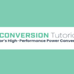
Overvoltage surges have a variety of causes that result in different waveforms (Figure 1). The possible sources of surges are many and varied, including hot plugging modules in a system; large load changes on the power line; long cabling or cabling that runs in parallel with other systems can experience induced surges, and; special environmental considerations such as equipment in a car or truck that connects to the vehicle battery or equipment in challenging outdoor locations that can be struck by lightning.
Surges generally have a similar rise time and half-length, regardless of their cause, simplifying the process of surge modeling. A standardized surge applied through a combination wave generator (CWG) is defined by IEC 61000-4-5. To simulate the cabling and interconnect resistances in a typical system, the CWG is defined with a 2Ω output impedance.
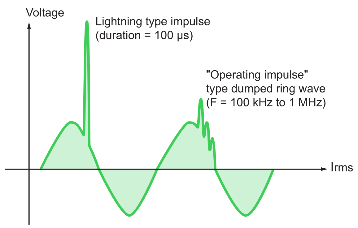
Current and voltage waveforms are defined by IEC 61000-4-5 (Figure 2). The current waveform is defined as a short circuit condition, while the voltage waveform is defined as an open circuit. The voltage waveform is longer than the current waveform. The open circuit voltage waveform is defined with a 1.2μs rise time with a 50μs half-length. The short circuit current waveform is defined with a longer 8μs rise time with a much shorter 20μs half-length. To have an effective impedance of 2Ω, the voltage waveform magnitude must be twice the current waveform magnitude.
Surge protection devices
Common SPDs include metal oxide varistors (MOVs), Gas Discharge Tubes (GDTs), and Silicon Avalanche Diode (SADs) or combinations of these devices. Each technology offers a different set of performance capabilities and tradeoffs.
Metal oxide varistors (MOVs) are the most common SPD. MOVs are made using zinc oxide, a semiconductor material with a variable resistance. Under normal operation, MOVs present a high impedance path to ground, but when hit by a voltage surge, the resistance of the MOV drops sharply and provides a low-impedance to ground. MOVs have a limited operating life and degrade when exposed to many small transients or a few larger transients.
Gas Discharge Tubes (GDTs) use an inert gas in place of the zinc oxide. Under normal operation, the gas is a poor conductor presenting a high-resistance. But when the voltage rises high enough to ionize the gas, it presents a low-resistance path and diverts the surge to ground. GDTs can conduct more current for a given size than other SPDs. Like MOVs, GDTs have a finite life expectancy and can take a few very large transients or a greater number of smaller transients.
Silicon Avalanche Diodes (SADs) can also be used to divert surge energy to ground, but they have a lower current capacity compared with MOVs or GDTs.
Resistors, capacitors, and/or inductors can be used together with MOVs, GDTs, or SADs to provide enhanced levels of protection.
Surge protector specifications
Clamping voltage, also called the let-through voltage, is the voltage that causes the SPDs to clamp or short circuit. While a lower clamping voltage may provide better protection, it is often associated with a shorter life expectancy for the SPD. UL 1449 defines several clamping voltages for SPDs. The standard clamping voltage used for 120 VAC applications is 330 V. Other common clamping voltages are 400 and 500 V.
Response time measures the time it takes for the SPD to initiate a short circuit once the clamping voltage has been reached. GDTs are slower responding compared with MOVs. However, response times under standard testing are not necessarily a useful measure for comparing various MOVs. All MOVs have response times in the range of nanoseconds, while standard test waveform surges last tens of microseconds. GDTs are slower but can usually handle much larger surges compared with MOVs. As a result, the two types of devices are often used together. Hybrid SPDs are available that combine GDT and MOV technology into a single assembly.
MOVs also have Joule (J) rating that defines how much energy a MOV can absorb in a single event without failure. MOVs can have ratings exceeding 1,000 J and 40,000 A. However, since the actual duration of a spike is only tens of microseconds, the actual dissipated power is low.
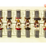
Higher J ratings can be achieved by connecting multiple MOVs in parallel, but this approach is fraught with challenges. Individual MOVs are imperfect devices with slightly different voltage thresholds and nonlinear responses. Some MOVs in an assembly can be expected to be more sensitive than others, resulting in a phenomenon called current hogging, where the more sensitive MOV(s) conduct more current and turn on faster. As a result, when a surge hits, the MOVs turn on sequentially from the most sensitive devices to the least sensitive ones. This behavior has two consequences: The most sensitive MOVs experience greater stresses and have lower operating lifetimes. The actual J rating of the assembly is lower than the sum of the individual MOV J ratings. The effective J rating is dependent on MOV matching, and derating by 20% or more is usually required. These assemblies employ carefully matched sets of MOVs. Matching is done according to the manufacturer’s specifications, but it is still less than perfect.
Finally, if a MOV is subjected to a continuous overvoltage condition instead of a short duration voltage surge, it may go into thermal runaway, causing overheating, possible smoke, and even fire. UL 1449 requires that MOVs be protected against thermal runaway. In most systems, thermal fuses or thermal cut-off (TCO) devices protect MOVs from thermal runaway.
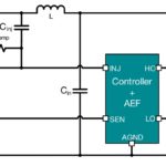
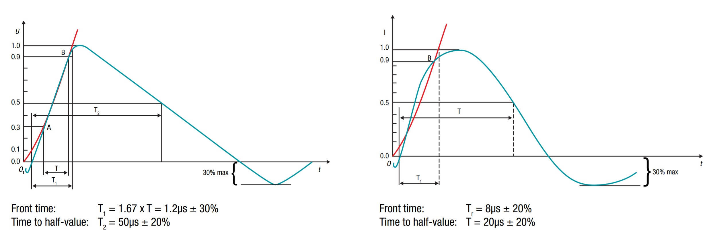
For the best protection, several MOVs with series TCO devices are placed in parallel across each of the three conductive pairs (L-L, L-G, and N-G) (Figure 3). In addition, a standard fuse is placed in the line to protect the system from an overcurrent condition. The fuse’s current rating is typically higher than the current flowing through the circuit during UL 1449 testing. Hybrid devices are available that combine a MOV and a thermal fuse in a single package, reducing component count and shrinking solution size.
Surge testing
The test method for input surge voltage testing is detailed in IEC 61000-4-5, and end system requirements define the limits. The test subjects the system to voltage spikes on top of the specified input voltage. The spikes simulate disturbances that may result from various sources ranging from lightning to large motor drives.
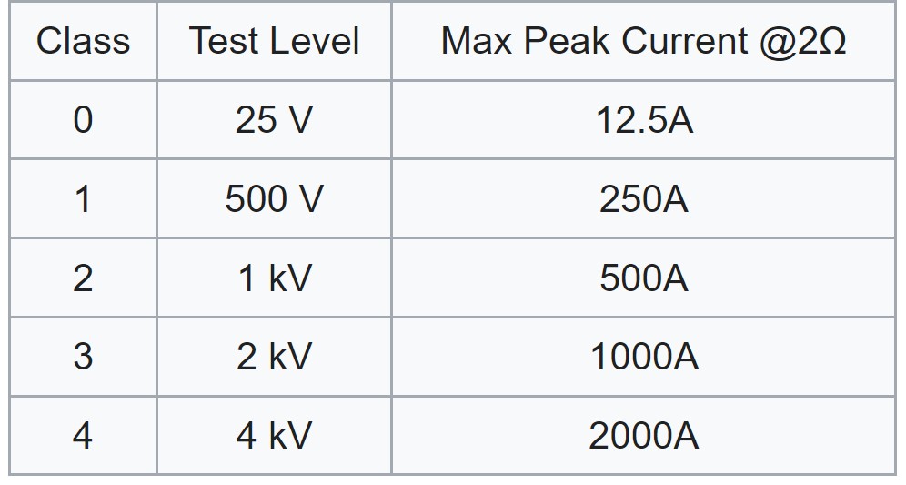
The installation class of the system determines the test levels (Figure 4). Most commercial AC/DC power supplies are Installation Class 3 devices and are tested for 2kV common mode surges between Line/Neutral and Ground, and 1kV differential mode surges between Line and Neutral.
In addition, the test specifies the required response of the system to the surge voltages, based on a three-level scale from A to C. Performance Criteria A requires that there is no change in the system operation as a result of the test. To meet Criteria B, the system experiences some change in operation or functionality during the surge event but auto recovers afterward. If user intervention is required to restore system operation after a surge event, the system meets Criteria C. If the surge damages the system, it fails the test.
How the voltage spikes occur, where they occur, what voltage levels and waveforms are needed, the frequency of the spikes and the duration between spikes are all detailed in IEC61000-4-5. But the standard does not detail how to determine whether the Performance Criteria Level is A, B, or C. That determination is up to the equipment maker.
Summary
Systems can suffer damage if left unprotected from AC line surges and voltage spikes. Various SPD technologies are available that enable designers to optimize surge protection networks for specific application requirements. In some instances, multiple SPD technologies such as MOVs, GDTs, and SADs are combined for a hybrid solution. MOVs are typically used in combination with TCO devices to provide protection from thermal runaway, as specified by UL 1449. IEC 61000-4-5 specifies the general input surge voltage testing method, including multiple surge test levels and performance levels for system classification.
References
Ceramic Varistors Technical Note, Nippon Chemi-Con
Demystifying surge protection, Texas Instruments
Designing with Thermally Protected TMOV® Varistors in SPD and AC Line Applications, Littelfuse
IEC EN 61000-4-5, Wikipedia
Lightning current surge and overvoltage protection, Wenzhou Arrester Electric Co., Ltd.
Surge Testing – An Overview, XP Power