The D7 robot vacuum from Neato Robotics in California boasts a lot of navigational features such as zone cleaning, no-go lines, and floor plan mapping. We tore down a D7 to see how these features
are implemented and to get a close look at the lidar unit that helps the bot find its way around.
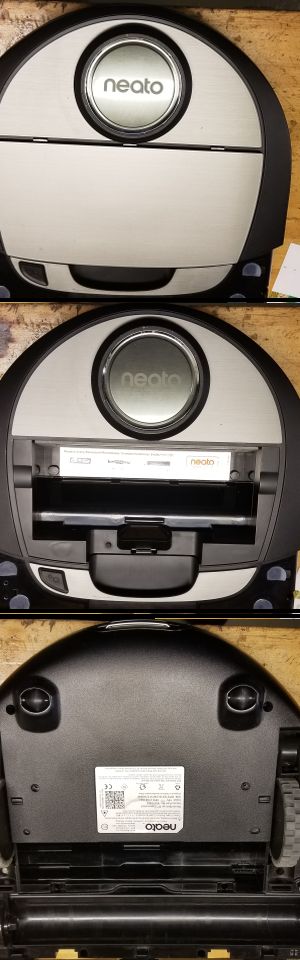
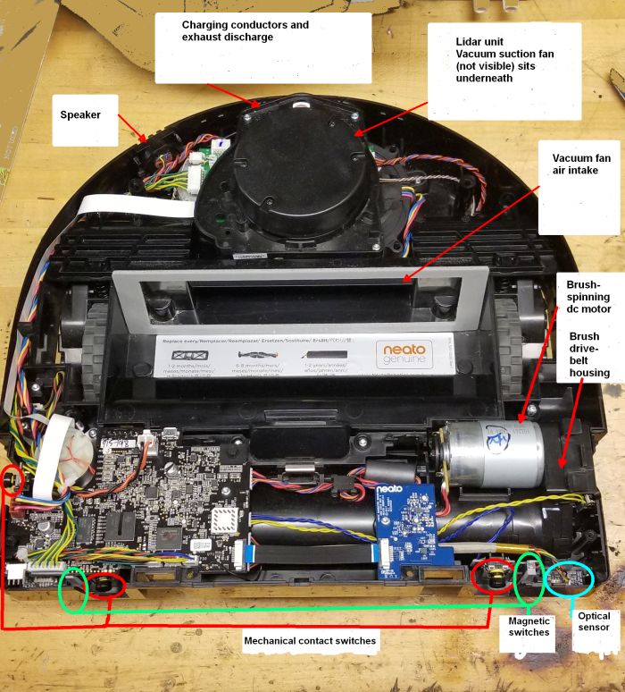
The D7 has two top covers, one around the front of the bot that can move slightly and actuate mechanical switches that serve as obstacle detectors when the vacuum bumps into something, and a main cover that’s attached with Torx screws. The main cover also holds the dust catcher and an air filter for the air output. Removing the top cover reveals the main electronics boards at the front of the bot as well as the lidar unit and mounts for the for various sensors and motors.
The D7 has a Wi-Fi interface to communicate directly with cloud servers for setup, account information,

and robot commands. The robot can vacuum without a cloud connection but cannot report maps or respect virtual no-go lines. The robot also communicates with a smartphone app when the user wants to give it manual commands that are not part of its learned mapping. The WiFi chip sits on the main circuit board which is visible near the front of the vacuum. This chip resides beneath a metal shield and is completely devoid of markings, so we couldn’t determine who manufactured it.
The main processor on the D7 is a Texas Instruments chip with a non-standard part number. Researchers in Germany who analyzed security aspects of the D7 report that the MCU is actually a custom AM335x Sitara processor chip with secure boot enabled, meaning the D7’s flash chip (a 4GB NAND from Kingston Technology) only contains an encrypted and signed system image; physical attackers can’t unsolder the flash chip to get at it. These researchers also report the MCU runs the QNX operating system and that overall, Neato sticks out on
the connected device market for using security techniques that are more common in industrial setups than in IoT gear.
The main PCB contains the level-shifting circuitry and charge management ICs for the robot’s 14.4-V battery. A point to note is that battery charge management takes place on this PCB, not in the external charger to which the D7 docks for a recharge. The charging connection consists of two horizontal metal bars sitting at the back of the robot in the exhaust outlet. To recharge, the robot backs itself into its charging dock so the two metal bars touch two large metal contacts on the dock. There is also a rectifier connected across the two metal charging contacts which is probably there to protect against accidental cross wiring during recharge.
There are six dc motors on the vacuum—one for the lidar, one for the side brush, one for the main brush, the fan motor, and one for each of the two driven wheels–and they all operate at 14.4 V.

The main PCB and daughterboard. Click image to enlarge.
Three of the motors can be operated at a variable speed and use speed feedback. These motors use a feedback
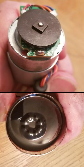
device consisting of a magnetic disk mounted on the motor shaft and a Hall effect sensor. Putting ferrofluid over top the encoder wheel reveals that it hosts eight magnetic poles. Thus the Hall sensor detects motor shaft rotation every 45°. Unfortunately there are no manufacturer markings on any of the motors so their rpm range–and the operating bandwidth of the speed feedback–can’t be determined.
There are two motor drive ICs (Texas Instruments DRV8800) on the main PCB that most likely handle the individual motors on the two main wheels. However, there is no motor-driver IC for the other speed-controlled motor that spins the main brush. The reason for the disparity: The main wheel motors must not only change speed but also go in reverse. The TI chips make possible the two-directional operation as well as operating a speed-control feedback loop. In contrast, though the main brush motor spins at different speeds, it always spins in the same direction. This allows its drive signals to be simple enough for the Sitara MCU to handle directly; basically the MCU monitors the brush-speed feedback loop and generates a pulse-width-modulated signal that determines the motor speed.
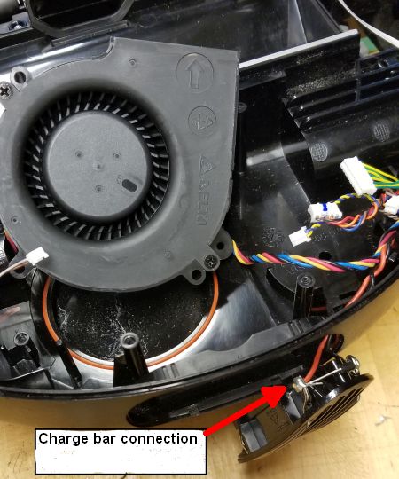
We should also point out that the fan in the D7 that generates the vacuum’s suction, made by Delta Electronics in China, is a variable-speed fan. (It is normally used for cooling server racks.) However, it appears that the D7 runs it only at the fan’s top speed.
The motors powering the lidar and side brush do so through O-ring style stretch belts. The fan motor sits in a blower housing and drives the centrifugal fan directly. The main brush motor drives the brush through a beefy timing-belt-style toothed belt. The motors for the two main wheels use a two-axis gear train that provides torque multiplication while also moving the axis of motion so the output is not in direct line with the motor axis. The output gear meshes with teeth on the inner diameter of the D7 wheels.
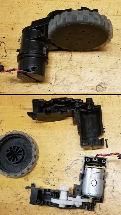
Both drive wheels have a simple suspension system consisting of a coil spring in compression positioned between the wheel assembly and the robot chassis. The point of the suspension system is to let the robot travel over uneven surfaces as, for example, moving from bare floor to a rug. When the robot wheels are completely off the ground, the springs are completely extended. A microswitch detects when each of the wheel assemblies are fully extended, signaling the D7 processor that the robot can’t move.
The lidar unit sits on a PCB positioned over-top the centrifugal fan. Central to the unit is a laser diode and an optical sensor both
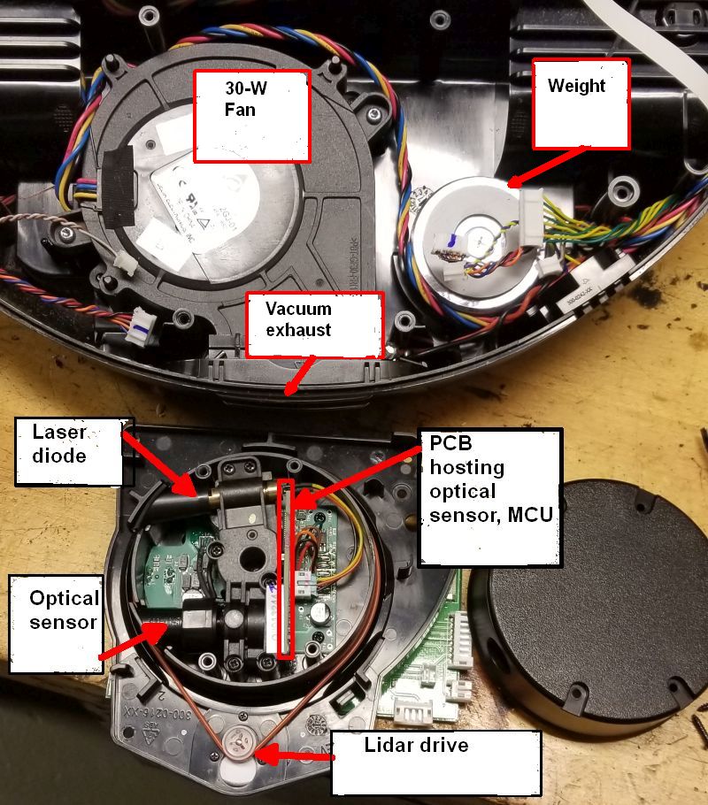
residing in a plastic mount which holds them at a fixed angle to each other so the sensor field-of-view intersects the laser diode beam. We measured the point of intersection using rulers and triangles and found it to be a bit more than two feet from the plastic mount.
The entire lidar module and all its electronics spins while the robot operates. Thus the D7 must get the lidar data off the spinning platform and back to the MCU somehow. The usual way of accomplishing this task is through a slip ring that provides continual connections for electrical contacts on the spinning platform. Interestingly, the D7 lidar doesn’t use a slip ring.
To get power to the lidar unit, the D7 uses an inductive pick up. AC power feeds to a fixed coil at the base of the lidar module. The
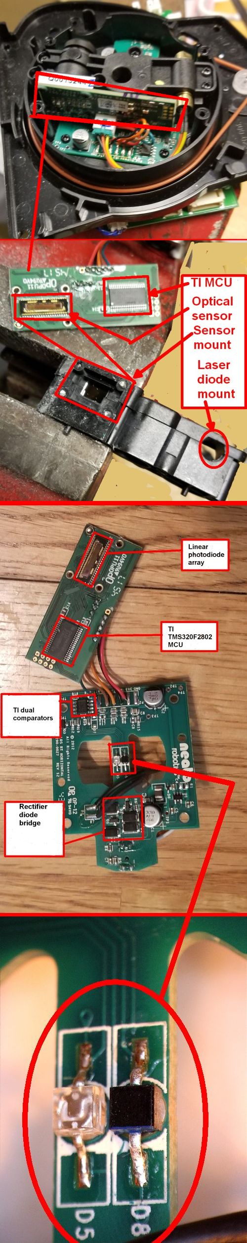
spinning lidar unit contains another coil concentric to the fixed coil. As the unit spins, ac is induced in the spinning coil that is rectified to dc by four diodes and a capacitor on the lidar board.
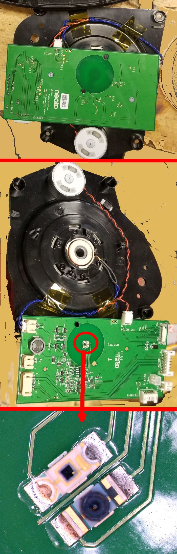
Optical sensors handle communication between the spinning lidar board and the rest of the robot without any physical connections. A PCB is affixed to the bottom of the housing that holds the lidar motor and spinning platform. This PCB serves as a central attachment point for several of the robot subsystems, but also contains a single photodiode and photodetector sitting at the center of the power-transfer coil. The two devices form an optical communication link to the PCB attached to the laser diode/photodetector housing. Another photodiode/photodetector pair on this board form the other half of the optical link. On both ends of the link, a dual-comparator IC from Texas Instruments seems to handle pulse shaping of the optical signals for use by downstream electronics.

The main components on the spinning lidar board is a Texas Instruments TMS320F2802 32-bit MCU and a linear photodiode array that picks up the laser diode reflections. There are no markings on the linear photodiode array, but it sits on a 40-pin package. If it uses an architecture similar to that of most commercial photodiode arrays, the pin-count implies that it contains about 35 photodiodes.
The D7’s lidar scheme is more sophisticated than that used in previous Neato bots, which employed slip ring connections. One aspect of the D7 construction which was unclear was Neato’s use of a small daughter board PCB off the main board. The daughter board apparently contained no active components, and its function was a bit mysterious to us. It is interesting to note that Neato vacuum bots released after the D7 no longer contain a daughterboard.