If you go to the Wikipedia page on absolute encoders, you’ll find descriptions of these devices mentioning multiple code rings, glass or plastic discs, and configurations of sliding contacts arranged so each contact wipes against a metal disc at a different distance from a
turning shaft. Actually, you’d be hard pressed to find any of these components mentioned in Wikipedia used in real absolute encoders made today. The main reason is that sliding contacts, multiple code rings, and multiple optical heads can be relatively complicated to assemble and thus a bit on the pricey side. So absolute encoder makers have largely gone to a much simpler configuration involving magnets and specialty sensors called Wiegand wires.
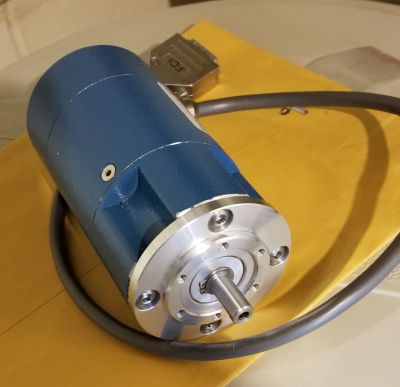
We tore down one such device made by Nidec Avtron Automation in Cleveland Ohio. This is an AV30 model designed for severe duty. Its housing has an IP65 rating and includes a beefy set of bearings. It also works over an extended range of temperatures. The particular unit we have puts out over 8,000 counts per revolution and provides position information in binary form over what’s called an SSI connection.
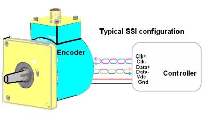 If you’re not super familiar with industrial encoders, the SSI protocol may be something new for you. It’s generally used only for absolute encoders. It’s a serial two-wire setup where the controller provides the clock pulses, so the encoder doesn’t need to generate a clock. A typical SSI connection has six wires: two for the clock signal, two for data, and two for power and ground. Each time the encoder receives a clock pulse, it puts a new data bit at the outgoing pin of a shift register. The data stream reflects the binary 12 or 14 bits representing a particular shaft position and then repeats.

The AV-30 outer housing is about five and half inches long and roughly three inches in diameter. It comes apart after you remove four modified set screws that are flush with the outer housing. What you see when you remove the outer housing might surprise you: The inside of the enclosure is basically empty. Instead of gazing at the encoder internals you see another smaller metal enclosure. Thus the outer enclosure is there to provide a seal against the elements and to hold the beefy bearings on the encoder shaft.
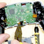
The smaller inner enclosure attaches to the encoder shaft with set screws. It is only about an inch and a half in diameter. The enclosure itself mounts to the outer enclosure in a way that permits its front shaft attachment to rotate. The small enclosure is basically a metal can that is press-fit to a header containing the rotating shaft bearing. Because of the press-fit connection, the metal can must be cut off to reveal the actual absolute encoder electronics.
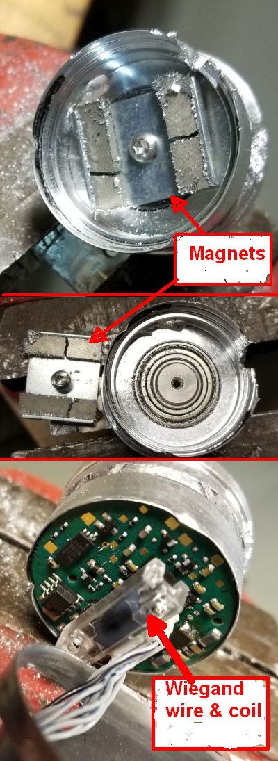
A peak inside the enclosure can reveals that it, too, is mostly empty. The PCB containing all the electronics is crammed into the front half-inch of the enclosure can, along with two magnets attached to the shaft which spin to provide the information about the shaft’s rotation.
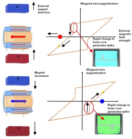
Absolute encoders like this Avtron unit are often billed as Wiegand wire sensors because they do, indeed, sense rotation using a Wiegand wire. Wiegand wire is actually a specially prepared Vicalloy wire (standing for vanadium-iron-cobalt). The special preparation gives it a hard magnetic outer shell and a soft magnetic core. The outer shell has a high resistance to being magnetized. If a magnet is brought near the wire, the outer shell shields the inner soft core from the magnetic field until the magnetic field becomes high enough, at which point the entire wire — both the outer shell and inner core — will rapidly switch magnetization polarity. This switchover happens in a few microseconds. And this switch-over is what’s called the Wiegand effect.
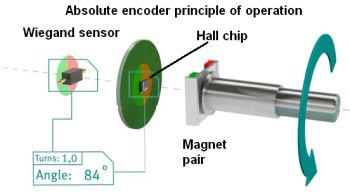
An important feature of the Wiegand effect is that the amount of energy generated with each reversal of the magnetic polarization is constant and completely independent of the rate of change of the external magnetic field, even if this happens slowly. The typical way of taking advantage of the Wiegand effect is to put the Wiegand wire in the middle of a coil, which is what you find on the PCB inside the Avtron absolute encoder. You find two magnets attached to the spinning shaft to generate the pulses.

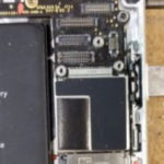
The spinning pair of magnets in the encoder make the Wiegand wire sensor put out two pulses for every revolution of the shaft. But you might wonder how you can get 4,096 different codes out of the encoder when the Wiegand wire only generates two pulses for every revolution. The answer is found on the other side of the PCB. There right in the middle of the board is a special Hall sensor IC from Melexis in Belgium. Conventional planar Hall technology is only sensitive to the flux density applied orthogonally to the IC surface. But the Melexis chip is sensitive to the flux density applied parallel to the IC surface thanks to a special material deposited on the CMOS die. This allows the chip to decode the absolute rotary or angular position from 0 to 360 Degrees using directional components of the flux density.
The only other identifiable chip we found on the encoder board was a Flash memory chip perhaps used to keep track of the encoder’s starting position. There was another chip on the board which we suspect is a variant of an ARM processor, but the chip markings are ambiguous.