• Skip to primary navigation
  • Skip to main content
  • Skip to primary sidebar
  • Skip to footer

Electrical Engineering News and Products

Electronics Engineering Resources, Articles, Forums, Tear Down Videos and Technical Electronics How-To's

  • Products / Components
    • Analog ICs
    • Connectors
    • Microcontrollers
    • Power Electronics
    • Sensors
    • Test and Measurement
    • Wire / Cable
  • Applications
    • Automotive/Transportation
    • Industrial
    • IoT
    • Medical
    • Telecommunications
    • Wearables
    • Wireless
  • Resources
    • DesignFast
    • Digital Issues
    • Engineering Week
    • Oscilloscope Product Finder
    • Podcasts
    • Webinars / Digital Events
    • White Papers
    • Women in Engineering
  • Videos
    • Teschler’s Teardown Videos
    • EE Videos and Interviews
  • Learning Center
    • EE Classrooms
    • Design Guides
      • WiFi & the IOT Design Guide
      • Microcontrollers Design Guide
      • State of the Art Inductors Design Guide
    • FAQs
    • Ebooks / Tech Tips
  • EE Forums
    • EDABoard.com
    • Electro-Tech-Online.com
  • 5G

The difference between active and passive antenna systems

March 3, 2020 By Martin Rowe

5G networks demand new antenna designs to deliver faster speeds for sub-6 GHz and millimeter wave (mmWave) communications. These new antenna technologies, however, often create a tech jargon that can potentially confuse readers.

Let’s set the record straight in terms of who is who in the 5G antenna designs. It starts with the difference between passive and active antenna domains.

In a conventional antenna system, a single passive antenna or several passive antennas in the form of arrays combine with radio chains to support communication systems. Here, it’s important to note that the passive antenna technology has evolved significantly over the past few years, and it’s now capable of supporting the legacy 4G systems as well as 5G NR systems in the 3.5 GHz frequency bands.

5G networks are increasingly adopting active antenna systems (AAS) to increase the capacity and coverage of radio streams. Active antenna systems feature a tighter integration of RF electronics with a massive-element antenna to enable miniaturization and boost efficiency.

The 5G base stations apply a high number of transmit and receive antenna elements for serving multiple users with parallel data streams. Here, active antenna system integrates the antenna array with the transceiver front-ends; an active antenna placed next to the RF module enhances communication throughput and reduces power consumption as well as cable losses.

An active antenna system usually includes interface amplifiers, low noise amplifiers, switches, and pre-drivers to address the transmit and receive requirements of massive MIMO in compact form factors. That also enables it to optimize the space on radio base station towers.

Passive-active antenna system
Another outgrowth from the traditional passive antenna systems, a passive-active antenna system combines a 5G active antenna with a passive base station antenna already used in the legacy cellular networks. It’s a two-in-one system that introduces a layer of active antennas on the existing cell sites and thus lowers the cost overhead associated with the installation of new antenna systems and cell sites.

Advanced antenna system (AAS)
There is another term in the 5G antenna jargon that shares the acronym “AAS” with active antenna systems: advanced antenna system (AAS). To show that active antenna systems and advanced antenna systems aren’t the same, here is a brief profile of advanced antenna systems and how they differ from active antenna systems.

2x2 active antenna

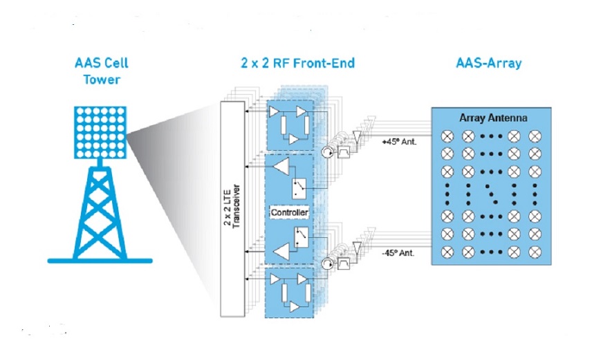
Active antenna systems employ intelligent integration of active transceiver array and passive antenna array into a single hardware unit. Image: Qorvo (Click image to enlarge)

An advanced antenna system or AAS comprises an antenna array closely integrated with the hardware and software required for transmission and reception of radio signals as well as signal processing algorithms to support the execution of advanced 5G communication features. It’s a key enabler in implementing the beamforming and MIMO techniques in 5G designs.

Advanced antenna systems provide greater steerability for adapting the antenna radiation patterns to rapidly time-varying traffic and multi-path radio propagation conditions. They enhance 5G network performance in both uplink and downlink.

You may also like:


  • What are RF waveguides? Part 1: context and principles
  • earth ground
    Poor earth ground on satellite dishes can put you in…
  • IoT antenna design
    Hidden pitfalls of IoT antenna design
DesignFast Banner version: 03e1dd97

Filed Under: 5G, FAQ, Featured Tagged With: qorvo

Primary Sidebar

EE Training Center Classrooms

EE Classrooms

Featured Resources

  • EE World Online Learning Center
  • CUI Devices – CUI Insights Blog
  • EE Classroom: Power Delivery
  • EE Classroom: Building Automation
  • EE Classroom: Aerospace & Defense
  • EE Classroom: Grid Infrastructure
Search Millions of Parts from Thousands of Suppliers.

Search Now!
design fast globle

R&D World Podcasts

R&D 100 Episode 7
See More >

Current Digital Issue

April 2022 Special Edition: Internet of Things Handbook

How to turn off a smart meter the hard way Potential cyber attacks have a lot of people worried thanks to the recent conflict in Ukraine. So it might be appropriate to review what happened when cybersecurity fi rm FireEye’s Mandiant team demonstrated how to infiltrate the network of a North American utility. During this…

Digital Edition Back Issues

Sponsored Content

Positioning in 5G NR – A look at the technology and related test aspects

Radar, NFC, UV Sensors, and Weather Kits are Some of the New RAKwireless Products for IoT

5G Connectors: Enabling the global 5G vision

Control EMI with I-PEX ZenShield™ Connectors

Speed-up time-to-tapeout with the Aprisa digital place-and-route system and Solido Characterization Suite

Siemens Analogue IC Design Simulation Flow

More Sponsored Content >>

RSS Current EDABoard.com discussions

  • Photovoltaic MOSFET Drivers - Voltage Rating
  • UCC28070A controller ramp circuit implemented incorrectly?
  • Timing question on RX code
  • Frequency of FM transmitter not changing
  • Altium Routing: through vias being split into two blind vias. Additional question about blind via costs / benifits

RSS Current Electro-Tech-Online.com Discussions

  • software PWM
  • 200mv pulse to 12v lock
  • Background of Members Here
  • UCC28070A ramp circuit is wrong?
  • Treadmill board component burn repair

Oscilloscopes Product Finder

Footer

EE World Online

EE WORLD ONLINE NETWORK

  • 5G Technology World
  • Analog IC Tips
  • Battery Power Tips
  • Connector Tips
  • DesignFast
  • EDABoard Forums
  • Electro-Tech-Online Forums
  • Engineer's Garage
  • Microcontroller Tips
  • Power Electronic Tips
  • Sensor Tips
  • Test and Measurement Tips
  • Wire & Cable Tips

EE WORLD ONLINE

  • Subscribe to our newsletter
  • Lee's teardown videos
  • Advertise with us
  • Contact us
  • About Us
Follow us on TwitterAdd us on FacebookConnect with us on LinkedIn Follow us on YouTube Add us on Instagram

Copyright © 2022 · WTWH Media LLC and its licensors. All rights reserved.
The material on this site may not be reproduced, distributed, transmitted, cached or otherwise used, except with the prior written permission of WTWH Media.

Privacy Policy