When you send an instrument to a calibration lab, what do you expect to happen? The comprehensive definition of calibration is a verification of instrument specifications by measuring actual performance using external lab standards, normally instruments, which have better performance than the thing they’re measuring and which are traceable to the International System of Units via one of the National Metrology Institutes.
A simpler definition is that calibration measures the actual performance of every warranted specification for every installed option. That’s what instrument makers such as Keysight Technologies say they do when one of their instruments come back for calibration. A point to note is that functional testing does not test actual instrument performance—instrument users want to know the actual performance of the measurements their instruments takes. Instrument makes often develop performance tests for their instruments. They’ll often caution that independent labs checking calibration may not run performance tests, only calibration tests, which often are different.
One aspect of calibration that is sometimes hard to grasp is the concept of measurement uncertainty. Consider a simple bounded specification with a high and a low  value. If the measured parameter is above or below the high or low value, the instrument is out of spec. The gray area arises when the measured parameter lies near one of the two bounds. At this point, the concept of statistical intervals and measurement uncertainty becomes important. Measurement uncertainty is formally defined as a parameter associated with the result of a measurement that characterizes the dispersion of the values that could reasonably be attributed to the measurement.
Here it is important to distinguish between measurement accuracy and measurement uncertainty. You would generally get a handle on the accuracy of a given measurement system by looking at the accuracy of the key specs that matter most, then decide of those individual error contributors are independent. They you might come up with a way of weighting each of the factors and combining them into an equation. This then goes into figuring an error budget.
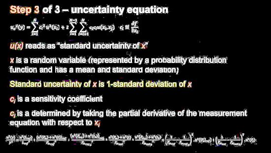
More specifically, the general approach is to analyze the sources of error, create a measurement equation for each of the performance tests, then model the errors and combine them per the outlines of GUM (ISO guide for expression of uncertainty measurement ), and then validate them. Problem is, that error model can be quite complicated for real-life test instruments. And most instruments have a number of performance tests. So the number of error models for a given instrument can grow to be quite large.
Makers of high-end test instruments actually compute error models for all their performance tests and code them into automated calibration software. These test results are what are reported in calibration reports citing measurement uncertainties.
Calibration reports will reference various standards. There is an international series of calibration standards called ISO/IEC Guide 25 as well as a European 45001 standard. EN 45001 and ISO Guide 25 merged and became ISO 17025 in 1999. There once was a military standard, MIL-STD-45662, often used for calibration in U.S. aerospace defense work. MIL standards were all repealed in 1994. Then the NCSL (National Conference of Standards Laboratories) released ANSI Z540.1 to replace the MIL standards. ANSI Z540.2 is simply the American version which basically just changes some of the wording for users in North America.
The GUM came out in 1995 and most instrument calibration standards now refer to it. Another standard called ANSI Z540.3 came out in 2007 and prescribes requirements for a calibration system with attention paid to measurement decision risk criteria, test uncertainty ratios, and use of calibration laboratories. Finally, there is ILAC (for International Laboratory Accreditation Cooperation) P14 and ILAC-G8. ILAC P14 is a critical requirements document that accredited calibration laboratories must comply with when developing uncertainty values for expressing uncertainty on calibration certificates. The G8 spec covers how to comply with specifications.
Perhaps the most interesting thing about these standards is that they define what calibration reports must look like. For example, calibration labs will provide a report about the instrument performance as they received it and a report laying out instrument performance after they worked on it. It is ISO 17025 that requires these reports. Such details can be helpful in determining whether or not the instrument was far enough out of calibration to give bad readings just before it was sent back for a calibration check.
Finally, calibration labs typically also provide what’s called a trace report consisting of all the instruments used in the calibration process, along with their ID numbers and calibration certificates. There is enough detail to see the exact path back to NIST or one of the other national metrology institutes, for each instrument used in the calibration.
Trace reports can also be helpful as sanity checks on whether or not specific functional tests took place during the calibration process. For example, in the case where a specific functional test required two signal generators, you would expect to see two signal generators listed on the trace report. If one only one was on the list, that specific functional test probably didn’t take place.