Automakers are struggling to deliver the first commercially available fully autonomous car (SAE Level 5). There are a lot of vision technologies and sensors available, but fine-tuning them has proved to be challenging. Cars need to “see” objects, moving or stationary, from far away enough to react and make driving decisions. One of the most popular sensors uses Light Detection And Ranging technology, known by the acronyms LiDAR, LIDAR, LiDAR or LADAR.
How does LiDAR work?
LiDAR sends out laser pulses — up to 160,000 per second. It can detect an object within a 1000- to 4000-foot range. LiDAR system accuracy varies, depending on if it is stationary or in a moving car. The frequency of the scanner also affects accuracy. It is not unusual to achieve accuracy to within about 0.6 inch. LiDAR paints the picture of what it “sees” by firing laser pulses and measuring the bounced back signals. By calculating the time delay, the distance of the object is detected. By doing this very fast, the processor can recreate its surroundings and paint a 3D picture.
Designing with an integrated solution
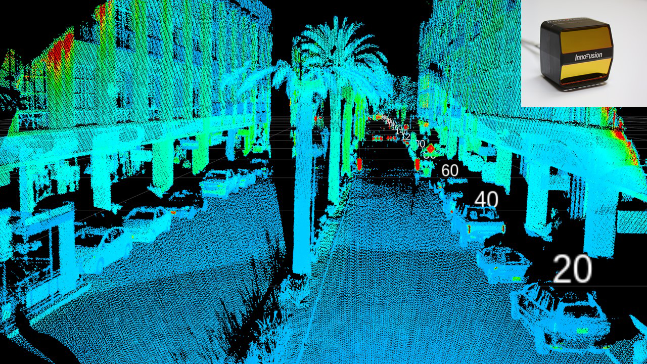
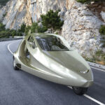
Figure 1: A high-resolution image of the surroundings is generated by the Cheetah, a complete LiDAR system. (Source: Innovusion Inc.)
It’s easiest to integrate a field-tested, off-the-shelf, all-in-one solution. At the recent Sensors Expo, California-based, Innovusion Inc. introduced the first dual rotating polygon optical architecture LiDAR system, “Cheetah” (Figure 1). It can detect objects at 200 meters with 10% reflectivity (Lambertian) with a maximum detection range of 280 meters. The system delivers a screen resolution of 300 vertical pixels at a frame rate of 10Hz, resulting in high-resolution images. This is done using 0.13-degree resolution over its 40-degree vertical field of view (FOV), and 0.14-degree resolution over its 100-degree horizontal FOV. Its best-in-the-industry performance opens the possibility of using the Cheetah system to replace multiple LiDAR units for SAE Level 3 driving. The laser pulse wavelength is 1550nm combined with a large aperture polygon. The sensor head dimension measures 112 x 145 x 105 mm (HxWxD) with the control box at 103 x 242 x 152 mm (HxWxD). The data transmission rate is at 1Gbps Ethernet, and the whole unit draws less than 40W.
Designing your own LiDAR
If you are a LiDAR maker or an OEM preferring to design your own LiDAR, you will need to select individual components for the job. What are the components of a LiDAR system? A basic LiDAR system consists of the semiconductor laser generator and a photodiode sensor to receive the bounced signals (Figure 2). Inside the system is a microcontroller or computer with digital processing capability. Additionally, not shown in the block diagram is the GPS unit to monitor the LiDAR system’s position. With many bounced signals, a 3D picture/image will be constructed to simulate the environment.
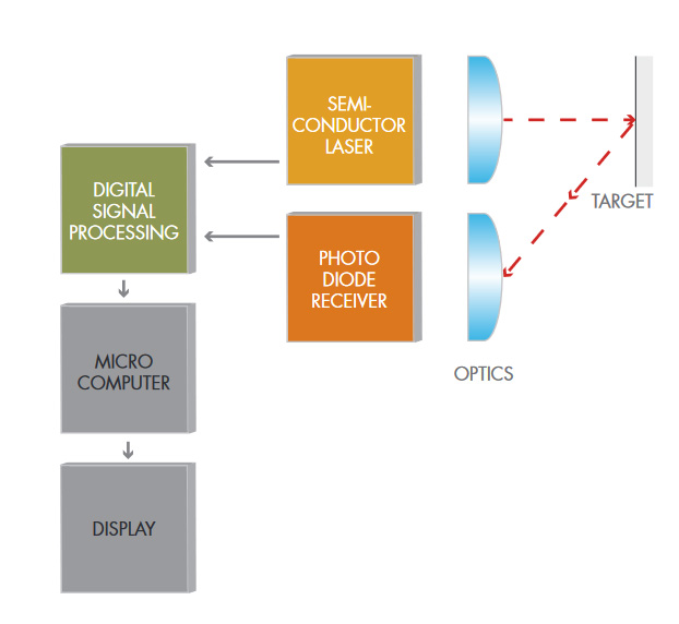
Figure 2: The LiDAR block diagram showing the unit with a laser transmitter and a photodiode receiver. (Source: Laser Components)
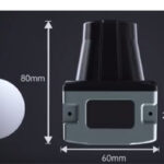
An example of a laser pulse diode transmitter is shown in Figure 3. Offered by Laser Components, the QuickSwitch Pulsed Laser Diode (PLD) was given the “Best of Sensors” award at the Sensors Expo & Conference 2019 and an AVT ACE award from Autonomous Vehicle Technology for its design. The unit comes in 850nm, 905nm and 1550nm laser wavelengths for different applications. 1550nm provides the best accuracy. It is capable of firing 200,000 laser pulses a second. Another consideration is the power output. Depending on the frequency, the QuickSwitch can deliver 100W. In general, a higher power diode can do a better job. Modules with built-in laser diodes are also available.
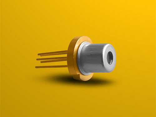
Figure 3: A hybrid pulsed laser diode (PLD), capable of firing 200,000 laser pulses a second, enabling faster and more precise 3D LiDAR scanning. (Source: Laser Components)
To include the signal processing and microcontroller capability, you can look into a silicon chipset (Figure 4). The color blocks represent chips available from Analog Devices. The GPS is the other commonly available component you will need.
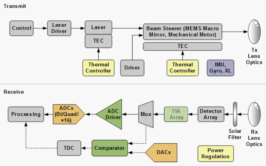
Figure 4: Block diagram showing various chips used in designing LiDAR. (Source: Analog Devices, Inc.)
In short, there are various design approaches a designer can take, including using an integrated system or discrete components. The former provides shorter-time to-market while the latter more flexibility. The LiDAR innovation for automotive is progressing quickly. It is expected to have better LiDAR products coming to the market in the next few years and, hopefully, this will make fully autonomous driving a reality sooner.


Leave a Reply
You must be logged in to post a comment.