BAW filters help overcome the biggest challenges facing Wi-Fi front-end designs, including thermal management, interference, and RF linearity.
Cees Links |Qorvo Wireless Connectivity
Smart homes are getting smarter. So they increasingly make heavy demands on their internet routers, so much so that traffic demands are exceeding the capacity of the single-router model. Retailers and businesses are also being overwhelmed by the ever-rising need for coverage and bandwidth.
As a result, new application models are evolving. Use of multiple routers, or nodes, in the home helps service more clients and handle more data. This new mesh network model implements techniques already used in commercial buildings, hospitals and college campuses via enterprise-level systems.
Not surprisingly, the mesh networking model also boosts RF complexity within the access point. Complexity also is rising because of new communication standards and better capabilities in communication hardware. The trend has brought several IoT-related challenges that include:
The need for wireless radios. Access points today incorporate more than just Wi-Fi — they also support Zigbee, Bluetooth, Bluetooth Low Energy (BLE), Thread, and narrowband IoT (NB-IoT). Operators are also finding ways to reach households that previously lacked such access.
More users within each home. Homes no longer have only one or two PCs and a few phones. Today, it’s common to find several computers, TVs, smartphones, wearables, security networks, wireless appliances, and more all connected to Wi-Fi and the internet.
Additional Wi-Fi bands. Units no longer have one 2.4 GHz band and one 5 GHz band. Now there are up to three individual 2.4-GHz and eight 5-GHz paths. The reason is the use of MIMO (multiple-input/multiple-output) and multiuser MIMO (MU-MIMO) paths within the Wi-Fi access point or node.
Shrinking size and expanded functions. Wi-Fi manufacturers are making Wi-Fi units smaller, sleeker, more decorative, and less obtrusive. They’re also making some units all-weather or adding functions such as night-light capability.
The additional RF chains generate more heat within the access point. They also make thermal management more challenging for Wi-Fi front-end designers. The higher temperatures also make RF tuning more challenging, especially when multiple RF chains must fit in the same box that once housed a single-channel Wi-Fi.
In a nutshell, temperature affects three RF front-end (RFFE) components: power amplifiers (PAs), RF switches and low noise amplifiers (LNAs), and filters. Engineers often balance among linearity, power output, and efficiency in each of the RF chains. Using optimized, highly linear power amplifiers or front-end modules (FEMs) optimizes system efficiencies, creating less overall heat. This practice also reduces processing inefficiencies. Wi-Fi design trends affecting power amplifiers include time division duplexing (TDD), optimizing error vector magnitude (EVM), higher modulation schemes, and efforts to moderate overall current draw on the system processor.
In the RF switch, insertion loss can also generate excess heat. When insertion loss rises and signal strength is low, the PA works harder to compensate and push higher outputs, which degrades efficiency. And less efficiency means more heat from the device. Use of high-linearity, low-loss switches keeps the insertion loss within specifications across the entire band.
Receive throughput depends greatly on LNA gain and noise figure. So although the LNA doesn’t contribute significantly to heat generation, heat degrades LNA noise figure, which can in turn drastically affect throughput.
BAW vs. SAW filters
As more LTE bands squeeze into the crowded global RF spectrum, the space between them is shrinking. In some cases, the transition between the passband and stop-band is as small as 2 MHz. This makes it almost impossible to meet requirements using traditional filter technologies. That’s because the variation in filter response, which is dominated by temperature drift, can exceed the width of the transition band itself. The result is unacceptable interference, high insertion loss, or both.
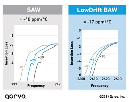
The thermal drift of SAW and BAW filters. If the filter drifts too much, as in the SAW figure, the RF power amp pushes out more power to compensate for the insertion loss. This consumes more current and reduces system efficiency.
The nearby figure illustrates the thermal drift of SAW and BAW filters. Temperature shifts can cause high insertion loss on the band edges, which could, in turn, cause a low output (gain or POUT) response from the RFFE. If the filter drifts too much (as in the SAW figure), the PA pushes out more power to compensate for the insertion loss. This draws more current and reduces system efficiency.
Although surface acoustic wave (SAW) filters are well suited for applications up to about 1.5 GHz, bulk acoustic wave (BAW) filters generally perform better with lower insertion loss at higher frequencies. BAW filters are inherently less sensitive to temperature changes than standard SAW filters. Diplexers, bandpass filters, and coexistence filters that use BAW technology with lower temperature drift help mitigate insertion loss and lead to good product thermals.
The circuits implementing different communication standards can also interfere with each other, leading to connectivity problems for users. For example, Bluetooth, Zigbee and Z-Wave are communication schemes for short and mid coverage ranges; Wi-Fi, 3G/4G LTE and 5G are standards operating at higher power levels and short and long ranges. And unlicensed (particularly within the IoT realm) networks are becoming more important as constrained wireless communications offload data to continually expand capacity. The challenge is to keep all these licensed and unlicensed bands and multiple protocols working in each other’s presence without interference.
Interference can arise within a device or between devices, including between wireless carrier signals or between circuits implementing different wireless standards. The most common interference scenario is Bluetooth and LTE with Wi-Fi because these technologies are so widespread.
There is also a possibility that the system’s multiple antenna architectures can interfere with each other. As a result, the coupling between the affected antennas (antenna isolation) is compromised. The foreign transmit (Tx) signal increases the noise power at the affected receiver, which degrades the signal-to-noise ratio. The receiver (Rx) sensitivity drops, which causes what engineers call “desensitization.”
Desensitization is a degradation of the sensitivity of the receiver caused by external noise sources. It results in dropped or interrupted wireless connections. Desensitization isn’t a new problem — early radios encountered receiver desensitization when other components became active — but now it’s particularly troublesome for wireless technologies, including smartphones, Wi-Fi routers, Bluetooth speakers and other devices.
There are three primary desensitization scenarios. First, two radio systems occupy bordering frequencies, and carrier leakage occurs. Second, the harmonics of one transmitter fall on the carrier frequencies used by another system. And finally, two radio systems share the same frequencies.
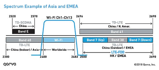
Several LTE bands — Bands 40, 7 and 41 — are close to the Wi-Fi band channels. Leakage into the adjacent Wi-Fi radio band is probable at both the high and low end of the 2.4 GHz band.
Several LTE bands — Bands 40, 7 and 41 — are close to the Wi-Fi band channels. Leakage into the adjacent Wi-Fi radio band is quite probable at both the high and low end of the 2.4-GHz band. Without proper system design, the cellular and Wi-Fi channels 1 and 13 can interfere with each other’s transmissions and receive capability.
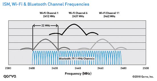
Bluetooth and Wi-Fi transmit in different ways using differing protocols, but they operate in the same frequency ranges. As a result, when Wi-Fi operates in the 2.4 GHz band, Wi-Fi and Bluetooth transmissions can interfere with each other.
Bluetooth and Wi-Fi transmit in different ways using differing protocols, but they operate in the same frequency ranges. As a result, Wi-Fi and Bluetooth transmissions can interfere with each other when Wi-Fi operates in the 2.4 GHz band. Because Bluetooth and Wi-Fi radios often operate in the same physical area (such as inside an access point), interference between these two standards can degrade the performance and reliability of both wireless interfaces.
Band edges and Wi-Fi coexistence
One way governments have tried to help consumers is by regulating the emissions and spectrum of electronic devices and requiring consumer products to undergo compliance testing. In the U.S., for example, the Federal Communications Commission (FCC) dictates that most RF devices undergo testing to demonstrate compliance to its rules. The agency enforces strict band edges by requiring steep skirts on the lower and upper Wi-Fi frequencies, to help with coexistence with neighboring spectrum.
As frequency rises, high-Q BAW is a good option for filter designs because it doesn’t suffer from bulk radiation losses that affect SAW filters. Also, BAW maintains steep skirts at band edges; SAW cannot match this performance at these higher frequencies.
There are two ways for Wi-Fi access points to meet this FCC requirement: Back off the power level on Wi-Fi channel 1 and 11, because they’re at the edge of the Wi-Fi spectrum; and use filters with extremely steep band edges.
High-Q BAW bandpass filters offer features that help Wi-Fi front-end designers overcome interference challenges, including extremely steep skirts that simultaneously exhibit low loss in the Wi-Fi band and high rejection in the band edge and adjacent LTE/TD-LTE bands. These filters are also physically small and can resolve coexisting Wi-Fi and LTE signals that are within the same device or near one another.
BAW filters demonstrate good power handling capabilities, allowing for implementation into high-performance, high-power access points and small cell base stations. These filters address the stringent thermal challenges of MU-MIMO systems without compromising harmonic compliance and emissions performance. This quality is critical to realizing reliable coverage across the full allocated spectrum.
It is useful to look more closely at the three ways that high-Q BAW filters make a difference for band edges.
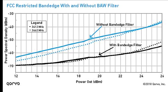
Band-edge response is better using a filter than without it. Filtering allows designers to push the limit on RF front-end output power while meeting regulatory requirements for power spectral density.
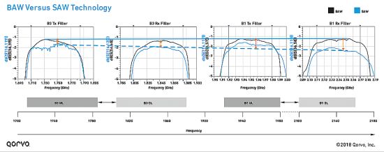
First, BAW devices have lower insertion loss, steeper band edges and better temperature stability than SAW technology at Wi Fi frequencies. At the higher bandwidths employed in standards like Wi-Fi, SAW devices can suffer from insertion losses that exceed those of BAW because acoustic energy radiates into the bulk of the SAW substrate. As frequency rises, high-Q BAW is a good option for filter designs because it doesn’t suffer from this bulk radiation loss effect. Also, BAW maintains steep skirts at band edges; SAW cannot match this performance at these higher frequencies.
Second, BAW filtering can help engineers provide seamless transitioning between interfering bands. Band-edge response is better with a filter than without it. BAW filters allow designers to push the limit on RF front-end output power while meeting regulatory requirements for power spectral density. This means band-edge BAW filtering lets operators and manufacturers deliver high-speed data and greater bandwidth by using spectrum that might be lost without filtering.
Third, high-Q BAW band-edge filters can extend the range in channel 1 and 11 by a factor of two or three. Wi-Fi designers normally must set the entire unit power to whatever the lowest band-edge-compliant power is for all channels. So, staying with the FCC example, if the compliant power at channel 1 is +15 dBm but channel 6 can achieve +23 dBm, the designer sets the entire power control scheme to +15 dBm. Use of band-edge filtering allows designers to set the power scheme to much higher powers, thus making it possible to use fewer RF chains.
CPE developers who don’t use band-edge filtering have difficulty meeting the FCC requirements on Wi-Fi band channels 1 and 11. In contrast, use of high-Q BAW band-edge filters allow the CPE designer to keep the power level the same throughout all the channels (1 – 11).
To paint the picture, consider the difference in user experience with and without band-edge filters.
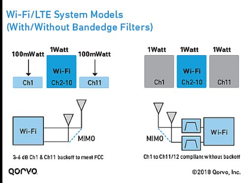
Customer premises equipment designed with band-edge filters (right) need not compromise Wi-Fi channels 1 and 11 when new users arrive, so the Wi-Fi unit doesn’t need to back off its power level to stay within FCC requirements. Football fans can watch streamed games without any buffering.
Without band-edge filters: Assume you’re in a house with several individuals using Wi-Fi and mobile phones. You’re on Wi-Fi using channel 5, streaming a football game and experiencing no buffering or interruption. But then new mobile users arrive and begin to consume your channel 5 Wi-Fi space. The CPE unit adjusts and bounces you to channel 1 to free up more space on channel 5. If the Wi-Fi unit lacks band-edge filters, your Wi-Fi strength and streaming degrade to the point where buffering occurs. Why? Because to meet the FCC requirement, the CPE unit must back off its power in channel 1 so it doesn’t interfere with adjacent cellular bands.
With band-edge filters: If the CPE unit had been designed with band-edge filters, channel 1 and 11 would not be compromised, and the power level would not require back-off. The streamed football game comes through without any buffering.
All in all, system capacity is an increasingly important criterion in Wi-Fi developments, together with thermal management and avoiding interference. BAW filters are inherently less sensitive to temperature change than standard SAW filters, and they generally deliver superior performance with less insertion loss at higher frequency levels. BAW filters can also overcome interference challenges, primarily because of their extremely steep skirts that exhibit low loss in the Wi-Fi band and high rejection in the band edge and adjacent LTE/TD-LTE bands.
References
Qorvo BAW filters


Leave a Reply
You must be logged in to post a comment.