• Skip to primary navigation
  • Skip to main content
  • Skip to primary sidebar
  • Skip to footer

Electrical Engineering News and Products

Electronics Engineering Resources, Articles, Forums, Tear Down Videos and Technical Electronics How-To's

  • Products / Components
    • Analog ICs
    • Battery Power
    • Connectors
    • Microcontrollers
    • Power Electronics
    • Sensors
    • Test and Measurement
    • Wire / Cable
  • Applications
    • 5G
    • Automotive/Transportation
    • EV Engineering
    • Industrial
    • IoT
    • Medical
    • Telecommunications
    • Wearables
    • Wireless
  • Learn
    • eBooks / Handbooks
    • EE Training Days
    • Tutorials
    • Learning Center
    • Tech Toolboxes
    • Webinars & Digital Events
  • Resources
    • White Papers
    • Educational Assets
    • Design Guide Library
    • Digital Issues
    • Engineering Diversity & Inclusion
    • LEAP Awards
    • Podcasts
    • DesignFast
  • Videos
    • EE Videos and Interviews
    • Teardown Videos
  • EE Forums
    • EDABoard.com
    • Electro-Tech-Online.com
  • Bill’s Blogs
  • Advertise
  • Subscribe

Cross-guide waveguide couplers carry up to 4-port interface

November 14, 2017 By Aimee Kalnoskas Leave a Comment

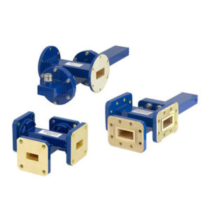
waveguide couplersPasternack, a leading provider of RF, microwave and millimeter wave products, has introduced a new line of cross guide waveguide couplers with 4 port, 3 port and 2 port with coax interface that work across C to K bands. Typical applications include instrumentation, test benches, product development and characterization.

Pasternack’s new line of crossguide directional waveguide couplers consists of 160 parts in three sub-categories: cross guide couplers (4 waveguide ports), cross guide couplers with terminations (3 waveguide ports) and cross guide couplers with terminations and waveguide to coax adapters (2 waveguide ports with either a SMA, type-N or 2.92 mm coaxial connection). These couplers operate over eight waveguide bands in the 5.85 GHz to 33 GHz frequency range. They are made with bronze waveguide bodies and are offered with EIA (CPR)-style flanges or UG-style flanges per military standard. These cross guide couplers are available with coupling factors from 20 to 50 dB.

“This family of cross guide couplers is offered in three different configurations: the coupler itself, the coupler preassembled with a termination or with a termination and a coaxial connection. Ordering these couplers couldn’t be easier, they come preassembled out of the box and, as with all of our products, they can be shipped the same day they are ordered,” said Mark Blackwood, Product Manager.

Pasternack’s new crossguide directional waveguide couplers are in stock and ready for immediate shipment with no minimum order quantity.

More information: Pasternack, 17802 Fitch, Irvine, CA 92614, 949-261-1920.

You Might Also Like

Filed Under: Applications, Wireless Tagged With: pasternack

Reader Interactions

Leave a Reply Cancel reply

You must be logged in to post a comment.

This site uses Akismet to reduce spam. Learn how your comment data is processed.

Primary Sidebar

EE Engineering Training Days

engineering

Featured Contributions

Five challenges for developing next-generation ADAS and autonomous vehicles

Robust design for Variable Frequency Drives and starters

Meeting demand for hidden wearables via Schottky rectifiers

GaN reliability milestones break through the silicon ceiling

From extreme to mainstream: how industrial connectors are evolving to meet today’s harsh demands

More Featured Contributions

EE Tech Toolbox

“ee
Tech Toolbox: 5G Technology
This Tech Toolbox covers the basics of 5G technology plus a story about how engineers designed and built a prototype DSL router mostly from old cellphone parts. Download this first 5G/wired/wireless communications Tech Toolbox to learn more!

EE Learning Center

EE Learning Center
“ee
EXPAND YOUR KNOWLEDGE AND STAY CONNECTED
Get the latest info on technologies, tools and strategies for EE professionals.
“bills
contribute

R&D World Podcasts

R&D 100 Episode 10
See More >

Sponsored Content

Advanced Embedded Systems Debug with Jitter and Real-Time Eye Analysis

Connectors Enabling the Evolution of AR/VR/MR Devices

Award-Winning Thermal Management for 5G Designs

Making Rugged and Reliable Connections

Omron’s systematic approach to a better PCB connector

Looking for an Excellent Resource on RF & Microwave Power Measurements? Read This eBook

More Sponsored Content >>

RSS Current EDABoard.com discussions

  • How to know if PIC works correctly or NOT ?!
  • optimum spacing between feed and sub reflector
  • Mean offset increase in post-layout simulation of clocked comparator
  • No Output Voltage from Voltage Doubler Circuit in Ansys Nexxim (Harmonic Balance Simulation)
  • No internet access after exchanging SIMCom A7682E against 7600G-H module

RSS Current Electro-Tech-Online.com Discussions

  • Fun with AI and swordfish basic
  • Simple LED Analog Clock Idea
  • Microinverters and storeage batteries?
  • PIC KIT 3 not able to program dsPIC
  • Is AI making embedded software developers more productive?
Search Millions of Parts from Thousands of Suppliers.

Search Now!
design fast globle

Footer

EE World Online

EE WORLD ONLINE NETWORK

  • 5G Technology World
  • Analog IC Tips
  • Battery Power Tips
  • Connector Tips
  • DesignFast
  • EDABoard Forums
  • Electro-Tech-Online Forums
  • Engineer's Garage
  • EV Engineering
  • Microcontroller Tips
  • Power Electronic Tips
  • Sensor Tips
  • Test and Measurement Tips

EE WORLD ONLINE

  • Subscribe to our newsletter
  • Teardown Videos
  • Advertise with us
  • Contact us
  • About Us

Copyright © 2025 · WTWH Media LLC and its licensors. All rights reserved.
The material on this site may not be reproduced, distributed, transmitted, cached or otherwise used, except with the prior written permission of WTWH Media.

Privacy Policy