Summary
This article discusses the newly emerging specifications, USB Type-C and Power Delivery (PD). Part 1 will introduce the USB 3.0 specification and its capabilities. Part 2 will explain various aspects related to the design of Electronically Marked Type-C cables.
Introduction
The USB Type-C is the newly introduced cable for USB. It is a simple, but powerful interconnect standard designed to enhance the existing USB 3.1 interconnect and overcomes major issues of legacy USB including:
- Fixed-plug orientation – Legacy USB cables have to be plugged in right-side up
- Fixed-cable direction – Type-A connectors need to be connected at the upstream while Type-B connectors need to be connected at the downstream
- Large connector design – prevents slim industrial designs

USB Type-C takes a step to address all of the above with these enhancements:
- Reversible plug orientation – Creates reversible cables through single-wire orientation detection. There is no wrong way to plug in a Type-C cable.
- Reversible cable direction – USB Type-C connectors are the same at both ends of the cable, making them omnidirectional.
- Slim industrial design with a 2.4-mm plug height allows for more flexibility in form factor.
In addition, USB Type-C allows easy implementation of low-cost power delivery up to 100 W.

USB is evolving from a data interface capable of supplying limited power to a primary provider of power while still being the ubiquitous data interface. Power delivered over USB has progressed from USB 2.0 (5V, 500 mA) to USB 3.0 (5V, 900 mA) to Battery Charging (BC) v1.2 (5V, 1.5A) to supplying power to more of our everyday devices.
The new USB Type-C specification extends USB power to 15W by increasing the current limit up to 3.0 Amps. USB Power Delivery (USB-PD) is the new specification designed to provide more flexible power delivery (up to 100W, 20V, 5A) along with data over a single cable. The intent is to permit uniform charging for laptops, tablets, USB-powered disks. and similarly higher power consumer electronics. Some international markets have established national mobile telephone charging standards around the USB interface, including the European Union and China. These two specifications allow for even more standardization for devices beyond mobile telephones.

USB-PD over Type-C adds a delivery sideband communication channel over a new Type-C signal called the configuration channel (CC). The CC wire is used for both USB Type-C VBUS power level notification and it is used for USB-PD negotiation and control. USB-PD uses PD messaging for 4 purposes including:
1) Start of Packet (SOP) enumeration
2) VBUS voltage and current negotiation
3) Role negotiation of three types of roles are also negotiated with USB-PD messaging. USB Data roles, VBUS Power roles and VCONN Power roles are the three types of roles that are negotiated with USB-PD messaging
4) Alternate Mode enumeration, negotiation and management are also done via USB-PD messaging.
Type-C combines power, data, and video in one cable

The Type-C interface includes:
- Two SuperSpeed USB lines with RX1/TX1 and RX2/TX2 that can also support alternate modes like DisplayPort, PCIe, etc.
- Two Sideband Use (SBU) lines for Alternate Mode
- Dp and Dn lines for Hi-Speed USB 2.0
- VBUS line for bus power
- VCONN line (only on the Type-C plug interface) for powering the cable controller
- Configuration Channel (CC) for PD communication
How the flip is handled
The Type-C Receptacle is designed to handle any orientation of the cable Plug. The USB Type-C receptacle is fully symmetrical. All power, ground, and signal pins are duplicated about the symmetry axis. This duplication allows the USB Type-C plug to be flipped with respect to the Type-C receptacle.

When the Type-C plug is rotated (as in Figure 5):
- GND, USB 2.0 and VBUS signals maintain connection. USB 2.0 signals are repeated in the top and bottom rows of the Type-C receptacle to maintain the connection in either orientation.
- VCONN or CC pin on the Plug may be connected to either of the configuration channel pins, CC1 or CC2 of the receptacle, depending on the orientation.
- One of the two Superspeed lanes maintains the right connection, which must be appropriately routed at the receptacle side using a SuperSpeed mux.
How plug orientation is detected
The USB Type-C specification describes how a Type-C upstream-facing port (UFP) applies Pull-Down resistors (Rd) on Configuration Channel pins CC1 and CC2 to signify that it is a device. The Type-C downstream-facing port (DFP) is required to have Pull-Up resistors (Rp) on CC1 and CC2. The resulting resistor divider is used to determine the Type-C device attach and detach; and the orientation of the Type-C cable plugs in each receptacle as only one of two CC pins is connected across the cable (as in Figure 6).
DFPs, specifically associated with the host USB data role, are typically the ports on a host, such as a PC or downstream ports of a hub, to which devices are connected. In its initial state, the DFP sources VBUS and VCONN. On the other hand, UFPs are the ports on a device or upstream port of a hub that connects to a DFP.
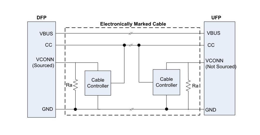
Type-C Electronically Marked Cable Assemblies (EMCA) are cables that require VCONN power to power the marker electronics inside the cable. These EMCA’s expose Ra termination resistors on the VCONN pin of the Type-C plug. Non Electronically Marked Type-C cables do not have electronics inside and have no need for VCONN power. These non-EMCA cables leave the VCONN pin floating on the Type-C plug.

Rp and Rd termination resistors on the Type-C receptacle CC pins make it possible to detect the connection event and identify the orientation of the Type-C plugs in the receptacles. The DFP and UFP monitor both CC pins on the Type-C receptacle for a voltage change from their unterminated voltages to detect the connection event. The UFP also monitors for VBUS as a second indicator of a DFP connection. Both DFP’s and UFP’s can determine the Type-C cable plug orientation on their respective ends of the connection. This is possible because only one of the CC pins is connected through the cable. After the connection and orientation is detected, the other CC pin is repurposed by the DFP as VCONN for powering the electronics in the USB Type-C EMCA plug if an Ra termination resistor is detected.
Power Delivery over Type-C
The USB Type-C specification allows for up to 15 Watts of power to be transferred from DFP to UFP on the VBUS and Ground signals. This 15 Watts of power can only be transmitted at 5 Volts when a “Type-C Only” solution is used. When you add the USB Power Delivery specification to a “Type-C Only” system, you create a “Type-C PD” system and can raise the VBUS voltage above 5 Volts to a maximum of 20 Volts and raise the VBUS current to a maximum of 5 Amps.
When operating in a “Type-C Only” system, the voltage divider of the Rp and Rd resistors that the DFP and UFP provide respectively determines the current limit of the VBUS power source. The UFP must detect this Rp/Rd voltage divider voltage and use it to determine the maximum current that can be drawn from the VBUS power source. This Rp/Rd voltage divider voltage is not static as the DFP can dynamically change its current limit as environmental variables of the charging ecosystem can change. The UFP must always monitor this voltage and obey the new VBUS current limit that is dictated by the DFP.
This behavior of a “Type-C Only” solution where the DFP dictates and a UFP obeys illustrates one weakness of a “Type-C Only” system. Negotiation does not exist in a “Type-C Only” system where a Type-C PD system has bidirectional negotiation of VBUS voltage and current levels. By adding USB-PD to a “Type-C Only” system and creating a “Type-C PD” system can you achieve the necessary flexibility of VBUS power negotiation.
When USB-PD is implemented, USB-PD Bi-phase Mark Coded (BMC) carried on the CC wire is used for USB-PD communications between USB Type-C ports. Figure 7 illustrates how the USB-PD controller connects to the CC wire and introduces BMC signaling to the USB Type-C cable’s CC wire. In the figure, only one of the CC lines (that which is connected through the cable) is shown.

How A Marker Chip Electronically Marks a Cable Assembly
An Electronically Marked Cable Assembly (EMCA) is a USB Type-C cable that uses a marker chip to provide the cable’s characteristics to the DFP. The electronic marking is accomplished by embedding a USB PD controller chip into the plug at one or both ends of the cable. These marker chips operate from VCONN power (or VBUS power as per the cable design). VCONN is a low voltage rail operating between 2.7 Volts and 5.5 Volts but is limited to 1 Watt of power. VBUS can be a high voltage rail up to 20 Volts. While marker chips operating off of VBUS can take advantage of more power a high voltage marker chip can also be more expensive. For this reason, most marker chips are powered by VCONN.
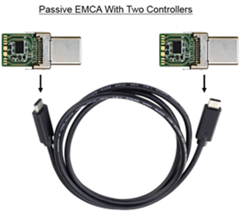
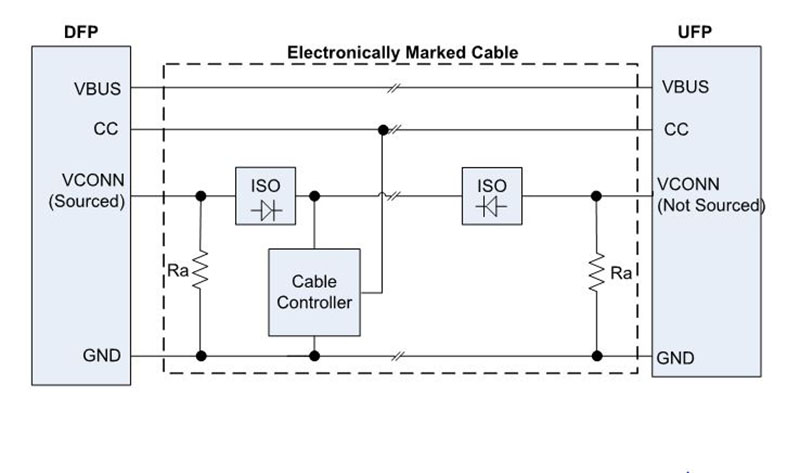
Some EMCA’s have a single marker chip on one of the paddle cards. Some EMCA’s will have two marker chips with one marker chip on each of the two paddle cards. If one marker chip is used, then a VCONN wire must be added to the cable that connects the two paddle cards. In addition, isolation must be provided on the paddle card to prevent both VCONN from being driven with voltage at the same time and colliding on the VCONN wire. The decision to design in two marker chips vs one marker chip should consider a few costs and benefits as listed here:
- If the cable is an optical cable with no copper wiring between the two paddle cards, then you must design two marker chips into the cable. This allows the DFP to communicate with the cable regardless of which end is plugged into the DFP.
- If the combined cost of adding in a VCONN wire that runs the distance of the cable added to the cost of adding isolation circuitry to safely combine the two VCONN wires is greater than adding two marker chips, you might consider adding two marker chips.
- At times, to simplify manufacturing and inventory handling it is easier to have two identical paddle cards instead of two unique paddle cards in the cable assembly.
From the DFP’s perspective, there isn’t a cost or a benefit with respect to EMCA’s having one or two marker chips. The DFP only powers one chip at a time and only communicates with the single marker chip. The cable controller stores configuration data related to the identity and capabilities of the cable. A few of these characteristics are
- Current rating of the VBUS wire
- Cable length
- Type of EMCA: Passive or Active
- Types of connectors on both ends of a cable: Type-C to Type-C, Type-C to Type-A, etc.
- Number of cable controllers in the cable: single or dual
- Type of USB signaling: USB 2.0, USB 3.1 Gen 1 or USB 3.1 Gen 2
- Vendor ID: 16-bit ID that identifies the EMCA manufacturer
- Product ID: 16-bit ID that identifies the EMCA product
- Support for Alternate Modes (e.g., DisplayPort, PCIe)
- Support for vendor-specific protocols (e.g., vendor-specific docking protocol)
The DFP has to discover cable characteristics along with the power requirements from the UFP using the 1st use of USB PD or SOP* enumeration. SOP* is a wild card identification that represents SOP, SOP’ and SOP”. These SOP* identifiers can be thought of addresses in the Type-C multi-drop connection. SOP represents the UFP in the connection. SOP’, pronounced SOP single prime, represents the EMCA marker chip that is the closest distance to the DFP. SOP”, pronounced SOP double prime, represents the EMCA marker chip that is the furthest distance from the DFP. SOP* enumeration is the first step of establishing the PD contract. Electronic marking shall only be implemented using USB PD BMC.
When is Electronic Marking necessary?
Electronic marking is needed in a Type-C Cable when any of the following apply:
- VBUS Current of more than 3 Amps is required
- USB 3.1 Gen1 or Gen2 is required
- Alternate Modes are required
Types of EMCA
There are two types of Electronically Marked Cable Assemblies (EMCA) within the USB Type-C specification. There are Passive EMCA’s and Active EMCA’s. The main difference in the two is that an Active EMCA offers signal conditioning of the SuperSpeed USB lanes such as redriver or retimer functions. Following are a few examples of each configuration.
- Passive EMCA: An EMCA that does not modify the USB data signals is a passive EMCA and can be designed in two ways – with or without the VCONN wire extending through the cable
Passive EMCA with one cable controller per cable plug, i.e. two cable controllers per cable. In this case, the VCONN wire need not extend through the cable (as in Figure 9).
- Passive EMCA with only one cable controller per cable. The VCONN wire will extend through the cable in this case and the isolation elements are needed to appropriately select the VCONN from one of the ends as the supply to the cable controller (as in Figure 9).
- Active EMCA: An EMCA with additional electronics to condition the USB data signals, such as redrivers. This allows the implementation of longer cables or for fiber optic cables.
It is common to think of a passive EMCA as a cable that doesn’t need power but this is not the case. Both Passive and Active EMCA’s require some form of power applied to them to power the marking circuitry.
** End Part 1 **
Click here to read Part 2: “USB 3.0 Cabling – Design Considerations“

