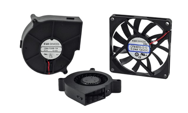
Natural convection cooling is often inadequate to meet the thermal management needs of electronic systems. In those cases, fans and blowers can move more air and keep the system within a safe operating temperature range. As well as being available in both ac and dc configurations, fans are generally categorized by the way the air enters and leaves the fan. In an axial fan, the air exits in the same plane as it enters. If the airflow leaves in a different plane, it is called a centrifugal design or blower. A centrifugal fan can compress the air, allowing it to deliver a constant airflow under different pressures.
The volume of airflow needed and the system’s static pressure are important considerations when selecting a specific fan or blower. Axial fans are most suitable for high airflow in systems with low static pressure, while centrifugal fans offer lower airflow but can deliver it against higher static pressure. The most common centrifugal fan design is the blower, which resembles an axial fan but typically expels air at 90° to the intake.

Axial fans are constructed with either steel ball bearings or sintered powdered bearings, often referred to as sleeve bearings. In low-temperature applications, sleeve bearings can operate and ball-bearing fans; however, at variable or high temperatures, ball bearings have longer operating lives and are more reliable.
Making less noise
Both audible and electrical noise are also important considerations when selecting a fan. In general, higher rates of airflow produce greater audible noise. Axial fans deliver lower airflow and are typically quieter than blowers. Optimizing the system’s overall thermal layout can reduce cooling needs, minimizing the required airflow and resulting in less audible noise.
DC fans are commonly used in electronic systems, and the dc motor generates electromagnetic interference (EMI). Fan- generated EMI primarily consists of conducted EMI in the power leads. In most cases, ferrite beads, shielding, or filtering can suppress unwanted EMI.
The portion of time a system spends at or near the worst-case thermal conditions (maximum ambient temperature and maximum power dissipation) is often a small fraction of the overall operating time and is an important consideration in designing a thermal management system. Under light load conditions, limited or no cooling may be needed. In addition to being unneeded, continuous full speed fan operation at less than worst-case thermal conditions has several disadvantages:
- Acoustic noise that is higher than necessary. Excessive fan noise can make the system less attractive to users and, in some cases, may exceed maximum noise levels mandated by regulations.
- Reduce overall system efficiency as a result of wasted power from running the fan more than needed.
- Reduce fan lifetime. For example, if a fan’s average speed is reduced to 50 percent of its rated maximum, its operating life can be approximately doubled, improving overall system reliability and availability and reducing maintenance costs.
Fan speed control systems
In addition to addressing the concerns outlined above, using a fan speed controller can enable the detection of fan failure before the system’s operating temperature rises significantly. That capability can allow the system to alert users to the problem before temperatures rise high enough to cause damage. In the case of mission-critical systems, a standby fan can be started up in the instance of the primary cooling fan’s failure. In systems with multiple cooling fans used under normal operation, the failure of a single fan can result in the controller increasing the speed of the remaining fans to help maintain the needed level of cooling.
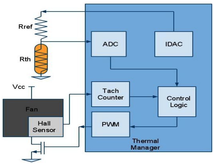
Fan speed controller ICs are available for use in designing forced-air thermal management systems. Those ICs can include several important functions beyond simple fan speed control, such as detecting fan failure and closed-loop fan speed control for improved system performance.
For cost-sensitive applications, linear control can be used to control fan speed. In a linear control system, the fan speed is changed by adjusting the voltage driving the fan. The lower the input voltage, the slower the fan spins. This has the advantage of simplicity and low cost. However, it has limitations. It is less efficient than pulse width modulation (PWM) control. And the linear regulators used to implement this control technique tend to be less efficient at lower output voltages, reducing efficiencies at low fan speeds. The fan’s operating voltage range is a further limitation of this technique and places a lower limit on how slowly the fan can rotate and maintain operation.
Due to the numerous drawbacks of linear control, PWM control is the most common technique used to control fan speeds. Implementing PWM control using a specifically designed fan controller IC can result in a cost-effective and highly-efficient thermal management solution. In addition to the simplicity of the control circuit, the dynamic range of fan speeds can be achieved is wider than is possible with linear control.

Two potential drawbacks of using PWM fan speed control are the generation of EMI and audible noise. It is usually possible to minimize the EMI on the power lines with relatively simple filtering. And the audible noise can be reduced by operating the PWM fan drive signal above the audible frequency range.
Types of fFans
Brushless DC (BLDC) fans are the most common type used to cool electronic equipment. BLDC fans are available in three variants based on the number of wires used, 2-wire fans, 3-wire fans, and 4-wire fans. The selection between these variants is based on cooling needs and cost and reliability considerations.
A 2-wire fan has power supply connections and is typically used in open-loop thermal management systems that don’t need feedback on the fan speed.

In addition to the power supply connections, a 3-wire fan has an output for a tachometer signal. 3-wire fans are controlled the same as 2-wire fans, by using the power supply connections. With a 3-wire fan, the fan motor and sensor for the tachometer share the same supply voltage. As a result, the tachometer only operates during the PWM signal period where it is driving the fan. The tachometer must be synchronized with the PWM and must be on long enough to provide a meaningful signal.
The tachometer signal can also detect fan failure or identify an impending failure of the fan. Before failing, many fans will spin more slowly at a given drive level than they did when new. By monitoring the fan’s speed vs. drive profile, it is possible to determine that the fan is beginning to slow, thereby allowing the fan to be replaced before it has completely failed. Some 3-wire fans have a locked-rotor signal in place of the tachometer output. The locked-rotor signal indicates when the fan stops spinning but does not provide the tachometer’s detailed speed information of a tachometer.
4-wire fans have all of the connections of 3-wire fans and add a PWM speed-control input. These fans are the easiest to control. Instead of modulating the power to the fan, the PWM input is used to control fan speed. That means that the power to the fan is continuously available, making the tachometer output continuously available. 4-wire fans can be operated at frequencies above the audible frequency range, eliminating audible noise. The recommended PWM frequency for these fans is typically between 15kHz and 30kHz, but some can operate as high as 100kHz. The PWM speed-control input is usually compatible with 3.3V or 5.0V logic.
So far, this thermal management FAQ series has looked at; “Basic principles of thermal management,” “Convection cooling components,” and “Forced air cooling keeps cool with fans and blowers,” The fourth and final FAQ will consider “Liquid cooling for high-performance thermal management.”
References:
Centrifugal fan, Wikipedia
Important considerations when selecting a fan for forced air cooling, CUI Devices
Robust system thermal management, Cypress Semiconductor
Thermal management handbook, Maxim Integrated


