Efforts at the Bureau of Standards 110 years ago paved the way for the cold-junction-compensation technique used today.
Thermocouples have long been used to make temperature measurements. They are simple, consisting of a pair of wires of dissimilar metals welded together at one end. They are rugged, operate over wide temperature ranges, and generate readily measurable voltages without requiring external excitation.
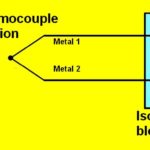
Unlike thermistors or mercury thermometers, thermocouples don’t directly measure a temperature of interest—instead, they measure the difference between a temperature of interest and a known reference temperature, usually called the cold-junction temperature. Figure 1 shows the basic setup. The welded thermocouple tip measures the temperature of interest. The other ends of the thermocouple wires terminate at the cold junction and present a voltage that depends on the temperature difference and the metals used to make up the thermocouple. Copper leads carry the cold-junction voltage to a DMM.

How do we establish the cold-junction temperature?
In the 19th century, researchers used ice-water baths, which any lab could reproduce, to establish a cold-junction temperature of 0°C. Over the years, researchers compiled comprehensive tables of temperatures and voltages for the various thermocouple types referenced to a cold-junction temperature of 0°C.
How many types of thermocouples are there?
The International Electrotechnical Commission’s IEC 60584-1 standard lists 10 types — A, B, C, E, J, K, N, R, S, and T—and provides voltage outputs as a function of temperature for each type. The National Institute of Standards and Technology (NIST) has data for types B, E, J, K, N, R, S, and T, which you can view here. All the IEC and NIST tables are referenced to a cold junction of 0°C.
How do I know which thermocouple type is best for my application?
The type you choose will depend on many factors—most important, the temperature range over which you plan to make measurements. For example, type B, whose positive and negative conductors are alloys with different percentages of platinum and rhodium, is suitable for the highest temperatures. The Figure 1 voltmeter shows a reading corresponding to a type B thermocouple measuring a 1,800°C temperature with a cold-junction temperature of 0°C. In contrast, the type T thermocouple, whose positive and negative conductors are copper and constantan, respectively, can operate down to cryogenic temperatures.
Isn’t it inconvenient to have to drag out an ice bath every time we want to make a thermocouple measurement?
In 1913, a researcher named Paul Foote at the Bureau of Standards, which has evolved into today’s NIST, made exactly that observation: “…for technical purposes and general commercial use, it is not always convenient to have an ice box at hand,” he wrote in “Note on cold-junction corrections for thermocouples” in the Bulletin of the Bureau of Standards, April 15, 1913 (Figure 2). He and the Bureau promulgated ways to make measurements at room temperature.

What do we do, just come up with new tables?
That could be a lot of work. We would need a different set of tables for every possible “room temperature” or other reference temperature we might want to use. For example, we might want to use a reference temperature higher than room temperature so we can regulate it with a simple heater, omitting the need for refrigeration if the room temperature got too high. The IEC and NIST tables provide voltage and temperature data at 1°C resolution over ranges of hundreds of degrees for each thermocouple type, so that’s a lot of data. A better approach is to find a way to use the existing tables—an approach called cold-junction compensation (CJC).
By way of example, consider Table 1, which lists a subset of the NIST voltage and temperature data for a type T thermocouple.
| Table 1. Type T thermocouple temperatures and voltages for a 0°C cold junction | ||||
| °C | mV | °C | mV | |
| 0 | 0.000 | 160 | 7.209 | |
| 10 | 0.391 | 170 | 7.720 | |
| 20 | 0.790 | 180 | 8.237 | |
| 30 | 1.196 | 190 | 8.759 | |
| 40 | 1.612 | 200 | 9.288 | |
| 50 | 2.036 | 210 | 9.822 | |
| 60 | 2.468 | 220 | 10.362 | |
| 70 | 2.909 | 230 | 10.907 | |
| 80 | 3.358 | 240 | 11.458 | |
| 90 | 3.814 | 250 | 12.013 | |
| 100 | 4.279 | 260 | 12.574 | |
| 110 | 4.750 | 270 | 13.139 | |
| 120 | 5.228 | 280 | 13.709 | |
| 130 | 5.714 | 290 | 14.283 | |
| 140 | 6.206 | 300 | 14.862 | |
| 150 | 6.704 | |||
Table 1. Type T thermocouple temperatures and voltages for a 0°C cold junction
I think I see how this works. Say we have a 40°C reference temperature and our thermocouple is generating a 12-mV output. The table shows that 12 mV corresponds to a 250°C temperature, so we just add 40°C to 250°C to get a measured temperature of 290°C, is that right?
No, that’s not quite right. In Part 2, we’ll look at why not and how to accurately apply CJC to your 12-mV example.